Yeah I appreciate his help, without him would of took a lot more confidence but him confirming for me makes it easier.
Yeah he’s 10-15 mins away from me lol
Yeah I appreciate his help, without him would of took a lot more confidence but him confirming for me makes it easier.
Yeah he’s 10-15 mins away from me lol
And take away from your pride of having done everything yourself? Great work by the way, I don’t mind all of the questions, now we can use this thread as a good tutorial for others. 
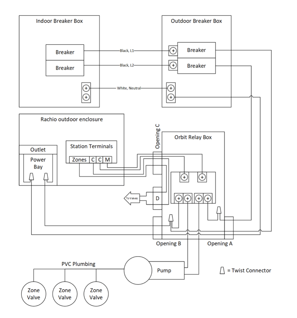
yeah will make wiring diagram later to post to see if i got it right and will get some conduit just because later when I get an adapter for pvc today after work
Now work on wiring diagram and to wait 24 hour to test for leaks and flow. Bought the wires and conduit.
Conduit from Relay in Mechanical timer box, to the rachio. Going to also run sprinklers cables through there. Make another hole in the mechanical timer box to run cables to sprinkler valves.
Thoughts?
Gonna see how people routed cables from valve to box neatly, not that I mind wires free but I like things clean.
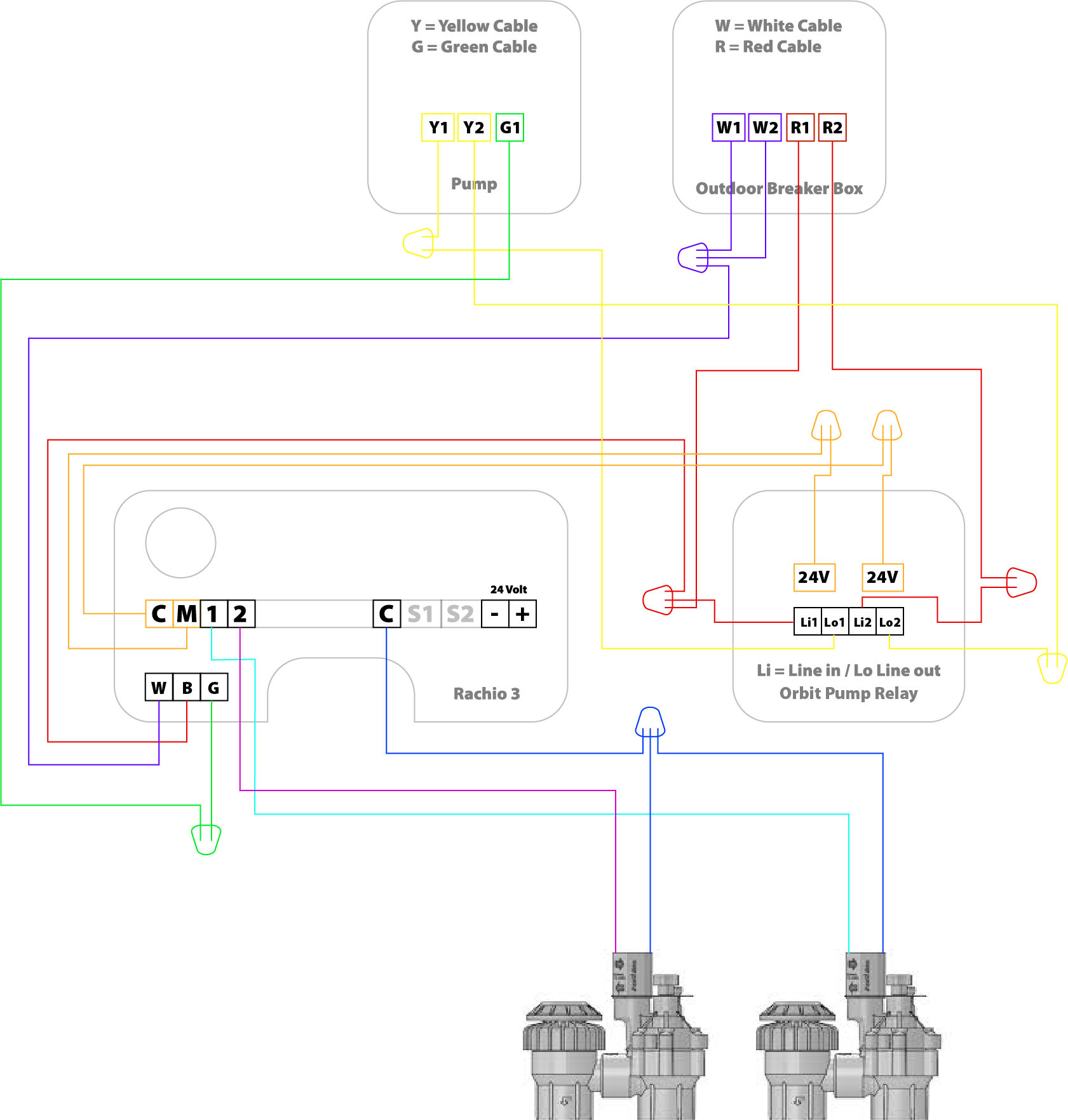
Wiring diagram coming soon
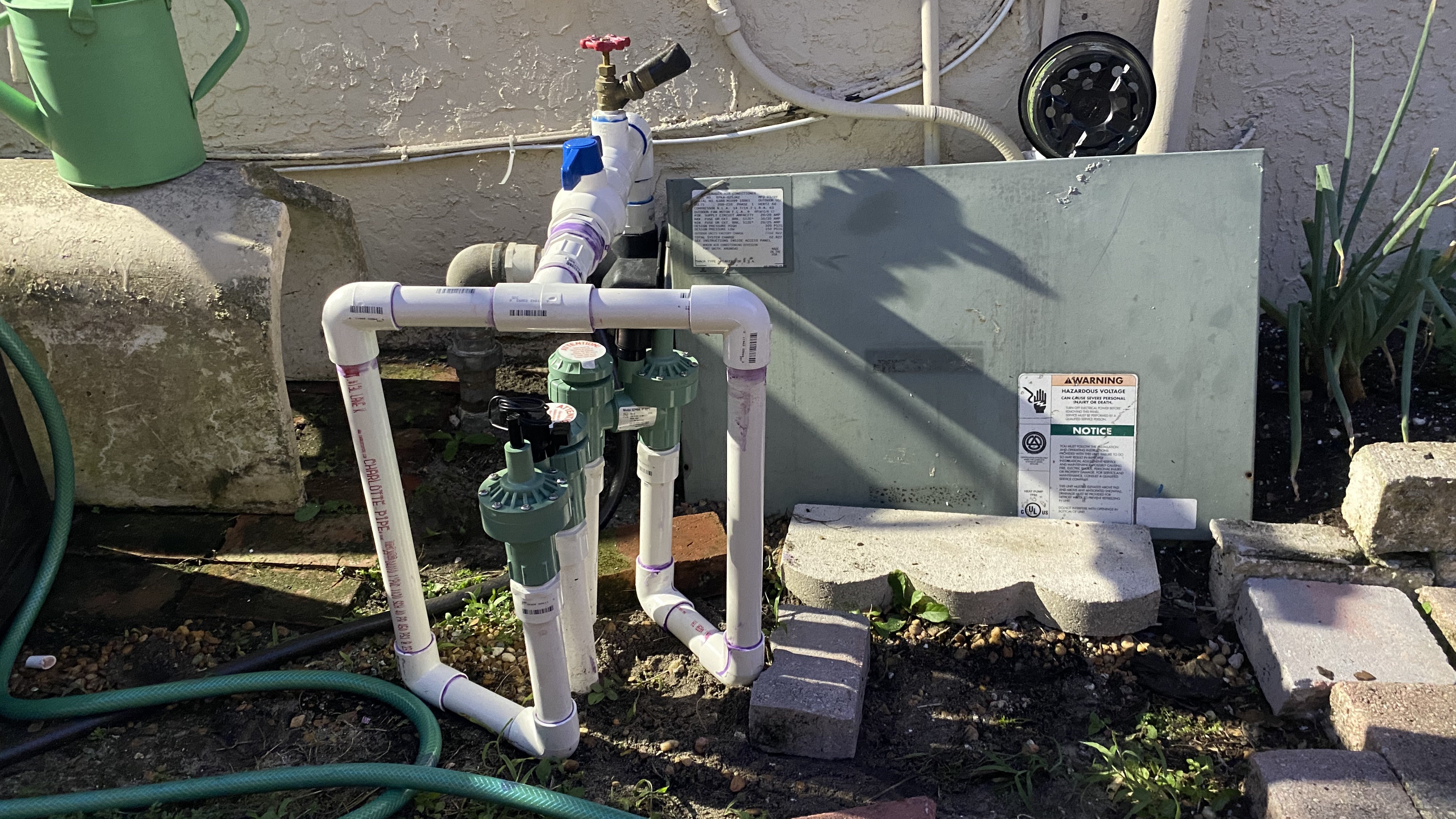
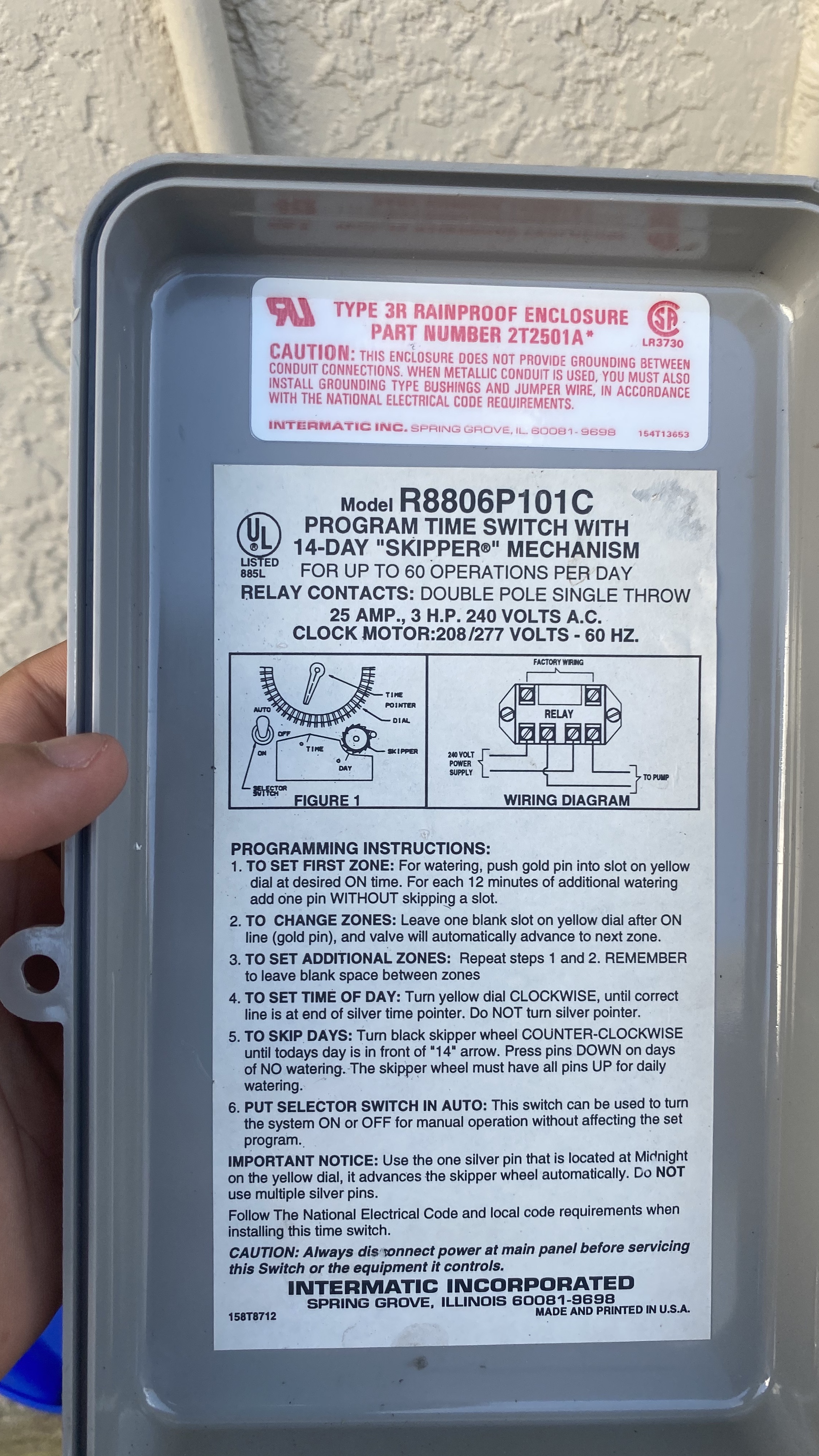
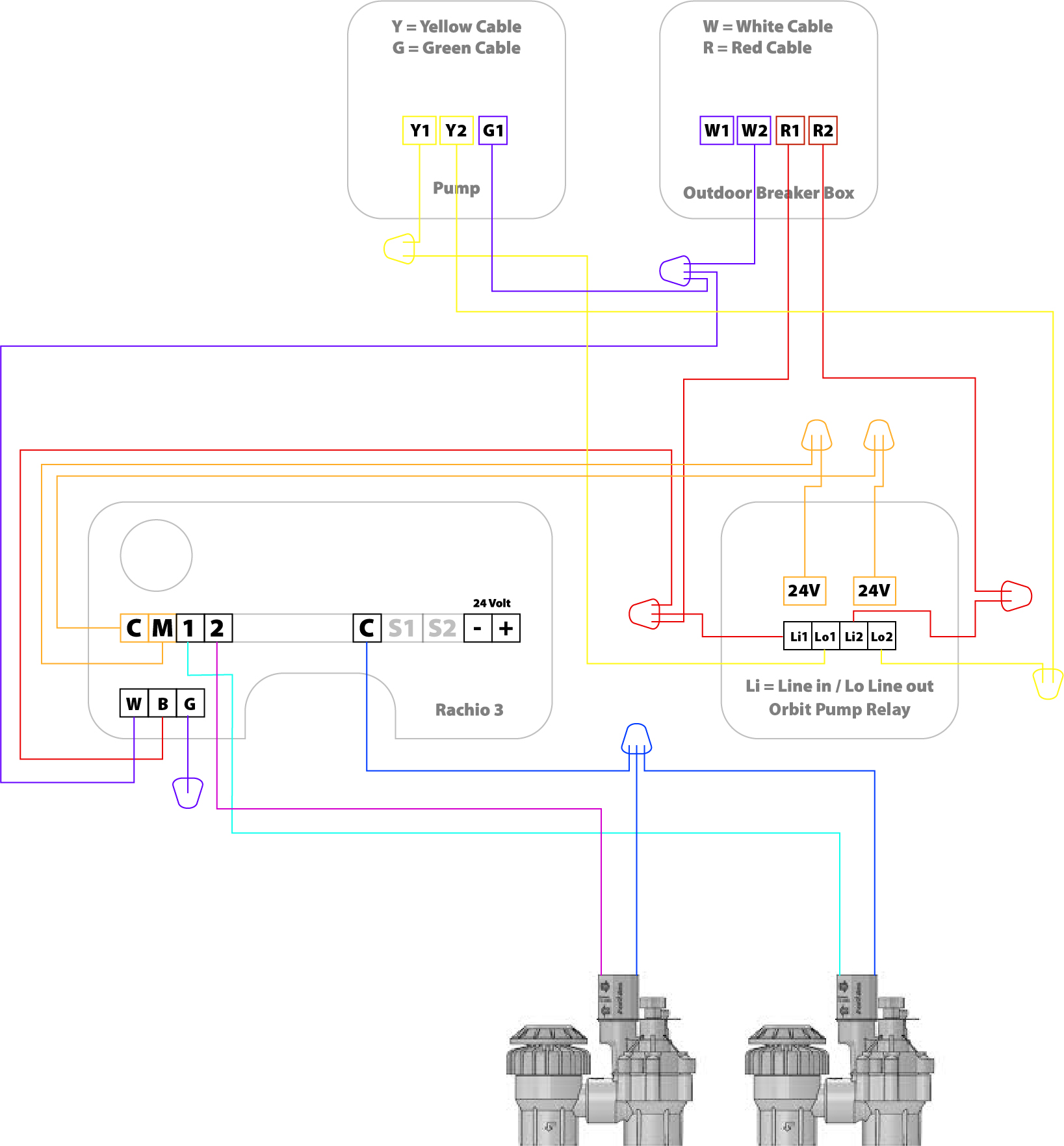
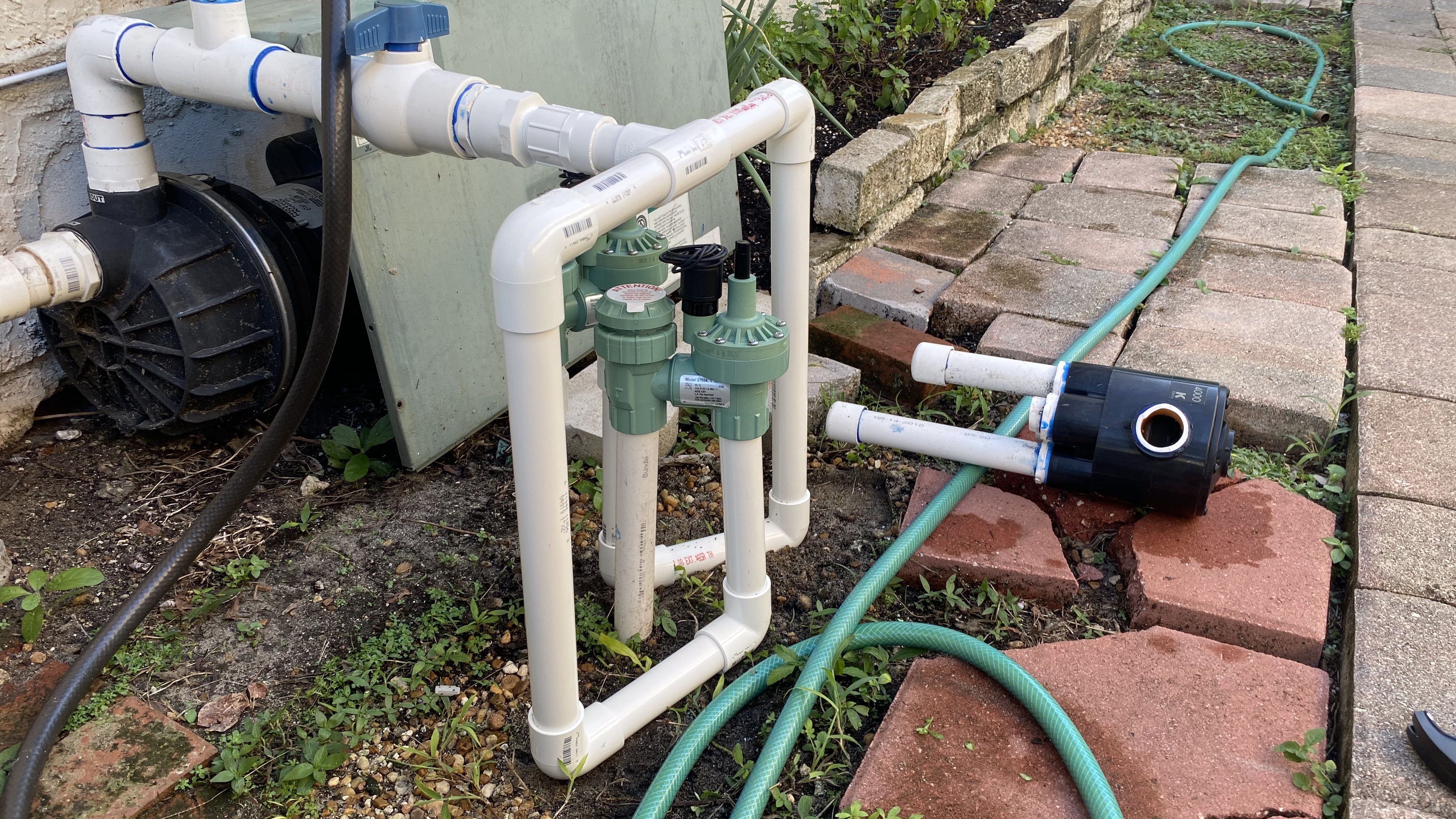
Alright here it is. I attached my mechanical box, to show how its connected. As well as the diagram I got off this forum somewhere that I based some of my decisions, then compared to my actual wiring right now.
If you look at the mechanical box, the wires coming out of the right side is from the breaker box and the bottom goes to pump.
Let me know what you think
You found one of my old drawings 
Do not ground your pump to the rachio controller, in your old timer it was done for simplicity, but the purpose of the green wire on the second photo is to connect to the white wire attached to the same nut. Because your breaker box is the first one downline from the meter, your Neutral (white) lines and ground (green) lines are interconnected there, thus it is possible to use a white wire (like they’ve done) to ground the pump. Fix: G1 terminal of the pump should be connected to W1 terminal of the breaker.
W1 and W2 terminals do not need to be tied together (no need for a wire nut), simply run the (white) line from W2 terminal to W terminal on your Rachio controller. Green (G) terminal can be left disconnected on the rachio controller (just cap it or connect it to the W line), since the power supply does not use it.
Otherwise you’ve got it, good job 
So the cables I bought (18 AWG) 4 Conductor today, those are a lot thinner then the cables inside the orbit relay. Will that be fine?
I might need more cable. I can run wire from Rachio to Valve and use 3 out of 4 wires. Then one wire from rachio to the pump relay… Actually I might have enough, forgot that my pump will already be where the cables are ran, was looking at my diagram of how they’re all separated for clarity.
I bought conduit that is 6ft. The website somewhere said have the rachio 15 feet away from pump? How far do I need to have it? Was thinking of putting how I photoshopped early on in this thread.
Will tape the wires before I take them off mechanical so I can label them. As in put tape around the cable and stick it to itself with enough room to write. Better yet I will use my label maker lol.
Since you are running the cable through the pump relay housing, you could use the wire nut to tie the relay common and the valve commons of of one line. (this will optimize the use of a four conduit cable you’ve bought)
So the cable (C, M, 1 & 2) goes from Rachio enclosure to the relay enclosure where the wire is cut and sipped back. (C and M) wires are used to run the relay, where as (C, 1 & 2) are moving onto the valves.You will likely end up using three wire nuts for this, or you can buy a terminal block (like this), which can be separated into the number you need (3?)
Do not worry about the wire size on the 24V terminals within the relay box, they’ve used the same gauge of wire as the line wires as a cost savings, 18 AWG is plenty to power that relay and then some.
The relay is low power, it should not cause any issues with the Rachio, do not worry about minimum distance as long as you have a strong wifi signal where you are planning on installing it.
Yeah I have good wifi and good signal strength beyond the house.
The actual relay pump housing, not sure where it comes out, its down there and I haven’t really looked at it, but was just planning to use the conduit I bought to run it down along the pump housing. Use the cable down there and just use 3/4 since I have to run the cable down there anyways for the zones.
For the one cable i’m not using in the wiring, I was just thinking of using electric tape or just putting a nut on both sides. I bought waterproof nuts in a big bag, so even though they provide nuts and the cables will be enclosed I’m going to use them on all the wires.
By relay enclosure / housing, I meant the plastic Orbit enclosure of the pump start relay that you are installing next to the rachio enclosure. There is no reason to open / make changes to the pump itself.
No need to terminate / hide unused cable next to your valves, simply leave it not stripped and wrap it around the cable to move it out of the way.
Theres that too.
But yeah I’m removing the mechanical timer guts and just screwing the relay in there like you suggested. But first i’ll try to see if I can remove the mechanical box completely and fit the orbit box in its place with the conduit already there (but I doubt it without a lot of work)
yea, save yourself the trouble, simply drill a small hole near the bottom of the old timer enclosure in order to allow the irrigation wire from the controller to enter. In this case I suggest you run separate cables to the relay and the valves. Having the valve wire follow the conduit to the pump is a good idea, there should not be enough interference to cause any issues.
Yeah gonna run conduit from rachio to the top of the box just to have space from the other two holes. Will route all the cables necessary from rachio to relay and rachio to vales through that, then have a separate exit to go to the valves from mechanical.
Actually might just get some more conduit for the small hole on racio where power goes for the relay cables. Then use big hole for the valves
Many ways to skin this cat, looking forward to how it will turn out.
In the interest of keeping the thread unbroken I’m replying to your comment here
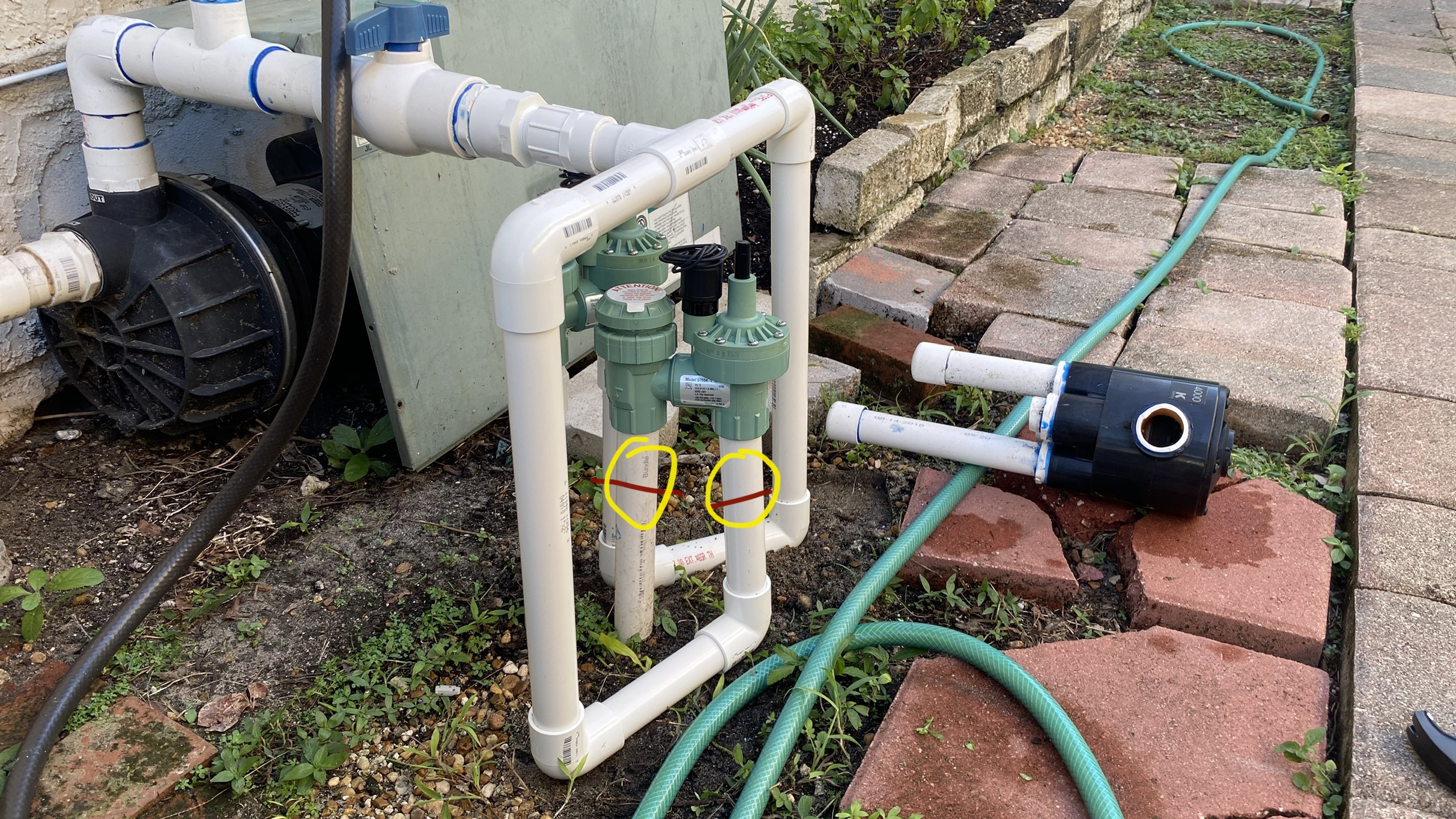
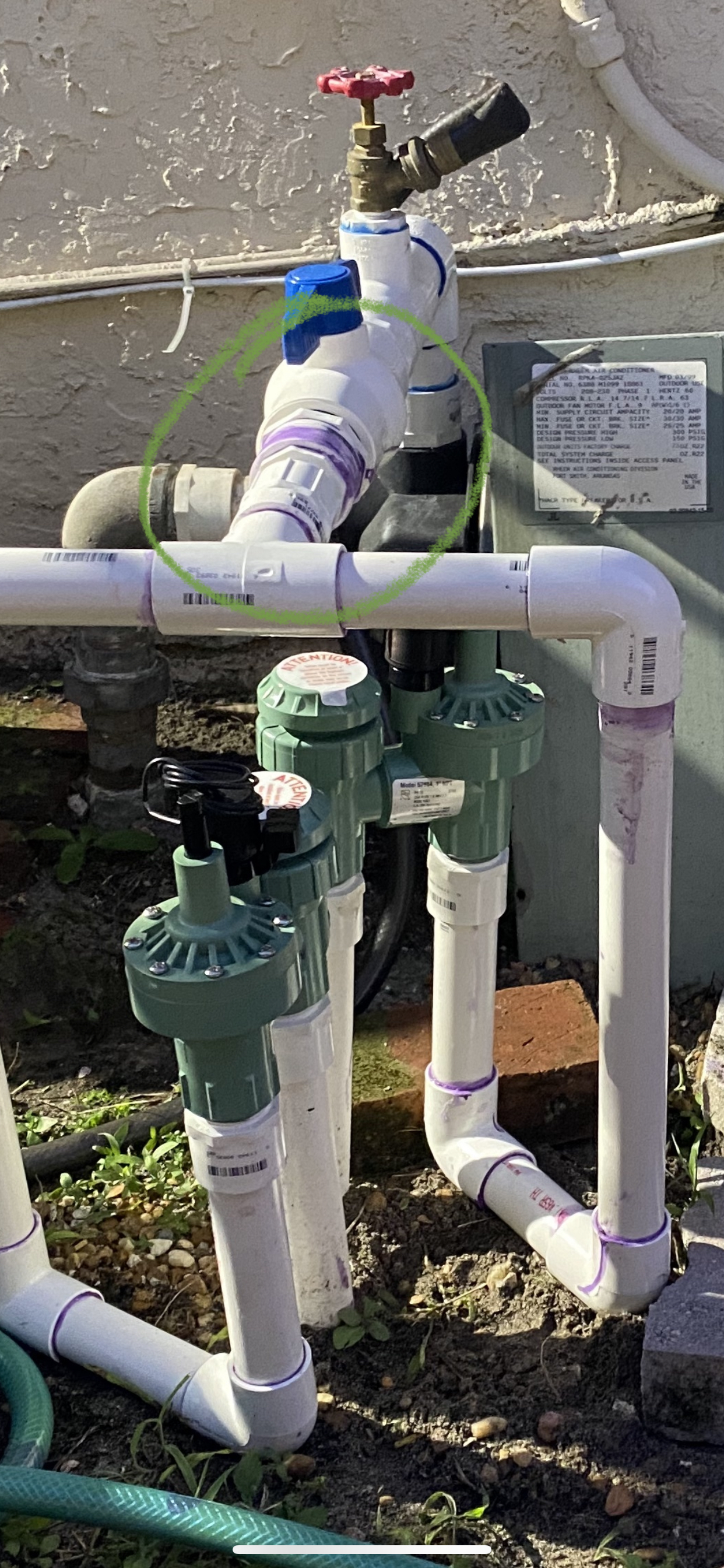
You can cut the pipe midway to the ground and install a twist union, so that in the future the repairs are easier:
You will likely need to make two cuts per valve, so that at the end you can completely remove the valve and fix the leak.
Unscrew the cut peace from the valve and reinstall it using the sealant, it is easier to apply generously and not worry about breaking the union:
I have a purple primer and and cement package one. I will google that so I can see how to do it better. As for the part with the cut off, cut and replace completely? But this time use sealant for the screw part?
You can fix the cut with new Union
Sealant is not a replacement for cement, use it in place of tape
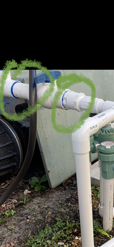
Not for the valves but where the cut off knob ball thing is. Those are are screwed and barely any room. Probably gonna cut and replace the pipes leading into that and find a screw glue.