I have about 26 zones so I need 2 controllers. I will have a shared common between the controllers because I don’t want to spend hours/days re-wiring boxes to isolate the commons. Finally, I have a master valve to add a little more in the mix
I saw the Rachio article on using the Isolator devices, but that would cost me over $100. For $10 I think I can do the same: KUP-14A15-24 relay and base.
Please see the wiring diagram and let me know if you think I’m crazy.
@janderson - what about the situation where both controllers are running at the same time? I think that the common would be returning through Controller A for valves from Controller B.
I’d also make sure the power supplies for both controllers are coming from the same electrical phase so the sine waves won’t be out of sync (e.g. same outlet with a multiple tap) with each other.
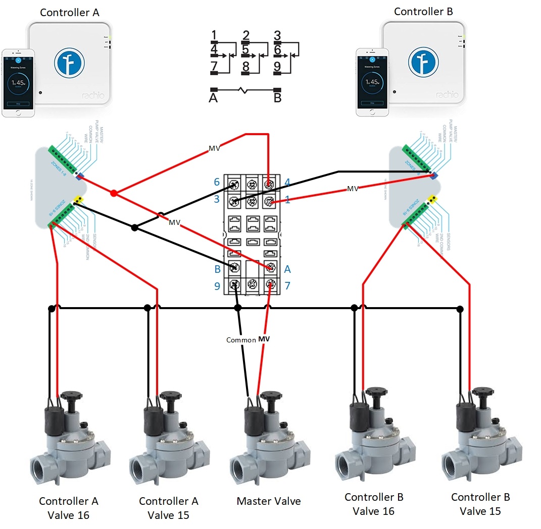
@janderson, I see no problem with your plan (as long as your properly schedule your controllers to never be active at the same time), good job. My only feedback is that you could accomplish a similar setup using a single SPDT relay, more on this can be found in an old post (link). Only difference is that you would use R1 terminal on your Gen 1 controller, instead of SC terminal shown on the original wire diagram.
The fact that above post discusses a hunter controller does not matter (it is simply a second controller), pump relay is essentially the same as the master valve for the purposes of this discussion and using SPDT setup has an additional advantage of not having one of your rachio’s potentially driving three loads (two valves & one relay) at the same time.
P.S. @DLane is right, ideally the commons for the valves driven by a particular rachio would be separate from the other valves and connected directly to the corresponding controller. If this is not possible, sharing only one line between controllers (such as your commons) can work without creating a potentially hazardous circuit.
Gene, you mention that the controllers shouldn’t run at the same time. I had planned that they wouldn’t and I figured that even if they did only valves connected to Controller A would work since Controller A’s common was the one being passed through the relay.
Then I started thinking about DLanes comments around phase. Now… if I had (2) 120v hots 180 degrees out of phase I can share a neutral/common without exceeding the capacity of the wire. With my limited knowledge this seems plausible with the 24AVC controllers too? So… instead of making sure the controllers were plugged in to the same phase, I would actually want to make sure they weren’t so as the common/neutral would be shared 180 degrees out of phase of one another. Maybe not, and if not can someone please explain why. If this does sound plausible, then I should be able to run both controllers at the same time.
I work for a utility company (computer department ) so I’ll try to find an electrical engineer tomorrow to get their thoughts (unless someone here has the answer first).
Oh… I’m only using the referenced relay because I had it on hand from a different failed experiment - lol
As long as only one line is shared between the controllers, such as your commons, the phases should not matter as the transformers within the power-supplies would provide a voltage isolation. This should hold true for any AC supply that only uses two power terminals (without a third GND terminal).
Phases come into play if/when a second line is shared, such as connecting both Master valve lines using a wire nut, instead of a relay. In case the controllers are on different phases, the voltage on the pins may go as high as 48 volts, in other words 200% of a nominal rating, killing the supply and/or controller(s).
Thanks Gene for all the great info! I think your comment around voltage isolation is helping me better understand what is happening and why the common from controller A can’t be used with the hot from Controller B like I’m used to with 120v house wiring (assuming out of phase hots so the neutral/common isn’t carrying more current than it is rated for).
I have the same issue with mixed input common sources (3 wire bundles). I have a Gen 3 16 and 8 zone. if I understand the thread, I can run a common wire from Unit a (common port) to a common port on Unit b to keep from rewiring the entire yard?
You need to use a relay as shown above. This is required to be NEC compliant and since I’m not an electrical engineer I can’t explain much as to why. Also, make sure you don’t run a zone on each controller at the same time because only 1 will work (whichever has the common connected via the relay).
Also, I asked some electrical engineers at work why they couldn’t run at the same time and they were sort of stumped. They normally work with high voltage so this isn’t their area of expertise. But that was enough of a reason for me to just use the relay. I really wish I could run both controllers at the same time. I’ll probably eventually isolate the neutrals (but that is a lot of work).
@Simonite does not have a master valve, unlike the configuration within this topic, so there is no need for a relay in his case.
@janderson the reason why you can’t run both controllers at the same time with your setup is that you are physically isolating the commons. This is not strictly needed as long as only commons are shared.
This has been proven in another topic
You can get both your controllers running at the same time by joining commons from your relay’s terminals 3,6 and 9. This should work as long as the original AC power supplies are used.
Thanks Gene, this is very confusing sometimes Glad you are here to help.
You mentioned above that the power supplies could see 48v and burn it out… I thought there was also a similar potential on a shared common if a valve on each controller was running. I also thought there was something related to NEC, but now I can’t find the reference. So… seems like I’m completely wrong…
You mentioned that the original power supplies need to be used, can you shed some light on why? Also would the power supplies need to be on the same 120v phase?
Perhaps it would be helpful to think of isolation in terms of the bird on a power wire. As long as the bird is touching only one wire, it is safe no matter the voltage within the wire itself. Sharing a single wire (commons) between multiple controllers, is like multiple birds sitting on the same wire. As long as birds are leaving each-other alone, we can have peace and quiet.
Isolating commons, such as with your original configuration is like shooing one of the birds away when the second one needs to land on the wire. Benefit of doing this is mostly superficial (useful only in case you power supplies may cause an issue).
The reason for recommending original power supplies, comes to us knowing that Rachio ships supplies with a good isolation from the mains. That just means that there is no voltage offset on the output which could be mismatched relative to another supply.
48V consideration comes from interconnecting a second signal, such as Master Valve without an isolation. In this case current would be generated in Supply A, travel though the M connection to Controller B and cause a voltage relative to a shared commons. Whether this voltage is 24V or 48V depends on the phase of the Supply B relative to supply A. If the phases match, voltage will be 24VAC maximum, if they do not, voltage could be as high as 48VAC when both controllers activate M output at the same time.
NEC actually already shares commons, aka Neutral, between phases & electric loads. As far as their coverage of low voltage circuits (such as 24VAC irrigation system), they are mostly hands off, as long as you are sure that the lines are, again, isolated from the mains.
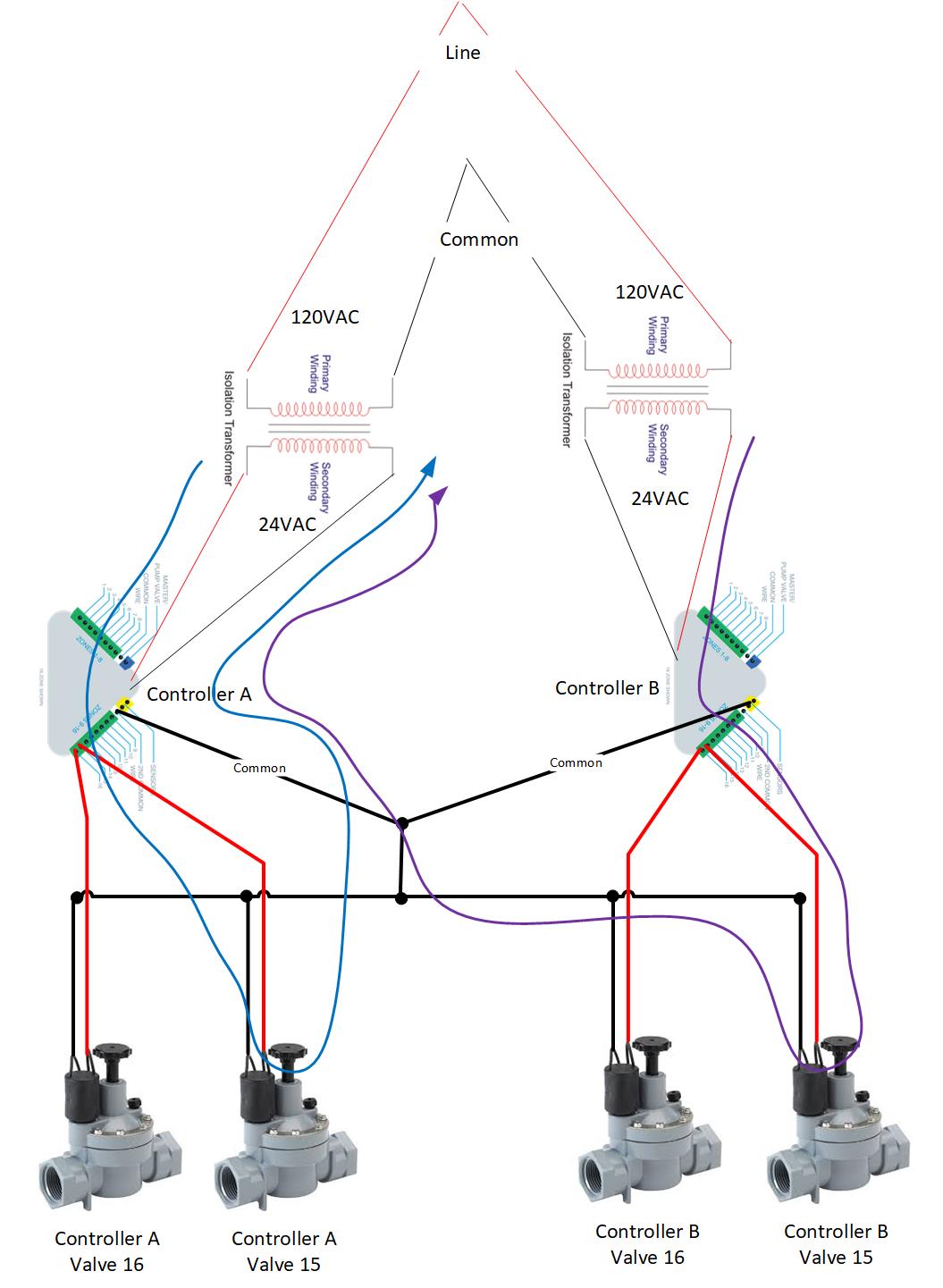
Hope you don’t mind another diagram I’m taking an online electronics class, but I’m guessing I won’t really understand how this works for a while longer. So… if you don’t mind helping me I really appreciate it. To me the blue line is what would happen if only controller A was running. However, if both controller A and controller B were running, what would prevent the purple line? And if the purple line is possible, isn’t it possible to exceed the capacity of the transformer? I’m appling what I know about 120v and if I have a 12/3 wire I can get qty (2) 20amp circuits out of it if the loads are on different phases (I’m sharing the neutral which is not overloaded because the (2) 20 amp circuits are on different phases - if they were on the same phase the neutral could see 40 amps and be overloaded).
You’ve actually outlined why the complete isolation with two controllers is not possible. Even if you disconnect the commons, there will still be a pathway via the solenoid as your purple line shows.
Now onto your question: When creating a current flow lines, remember that you have to work in loops. No matter where you start, ultimately you will have to end up at the same place in order for the current to flow. In your example, the purple line would take a path of least resistance, going right at the common fork into the right transformer (power supply), where it would complete the circuit.
Lets say, by random chance, a few electrons do take the purple path. That would mean that their charge has moved from the average of the right transformer into the average of the left. In case the left transformer ends up with that charge, it would become negatively charged, compared to the right transformer (since electrons are negatively charged). As similar charges repel one another, negatively charged left transformer would push electrons to the right, bringing the system back into equilibrium.
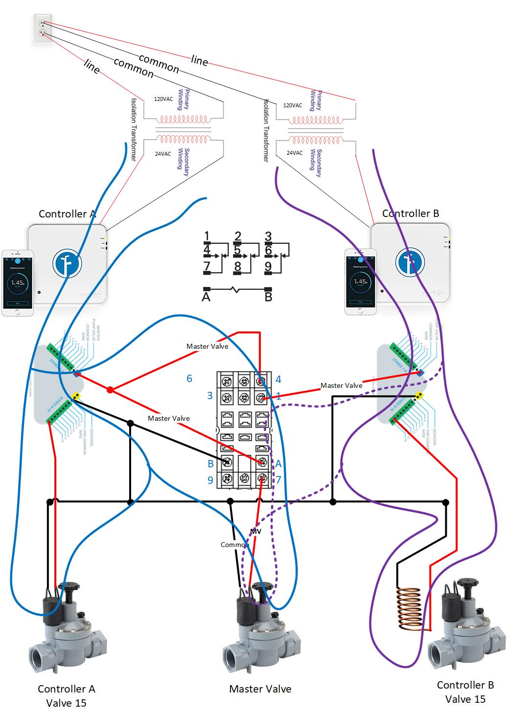
Thanks Gene for the awesome explanation! I had to go figure out what you meant by “complete isolation with two controllers is not possible” and that lead me to my final drawing I never realized the valve solenoids are just a coiled continuous wire and like you said, the 2 controllers can thus never be completely isolated (as my drawing demonstrates).
My new drawing includes my plan to change the master valve control relay. Now I can have both controllers running a valve at the same time and only one controller will supply power to the master valve. Blue line is current flows whenever Controller A is running, Solid Purple is current flow when a valve on Controller B is running (doesn’t matter if Controller A has a valve running), and the dashed purple is current flow to master valve when Controller B is the only controller running a valve.
Thanks again for spending so much time on this thread!


 ) so I’ll try to find an electrical engineer tomorrow to get their thoughts (unless someone here has the answer first).