I bought the Rachio 3 almost a year ago and just now getting to this project. I started installing this system then, as with almost everything I try to do on my own, hit a dead end so I found this forum. I understand this has been posted a few times, but I’m not quite understanding the exact process to get this to set up right. I have (“had”) an Intermatic Timer system, pump (well water), with what I believe was 4 zones or index valves? … I’m not exactly sure how that system was set up.
Running power to the rachio doesn’t look like it’ll be a problem … but I’m understanding correctly, with my current system, I’ll need a pump start relay to handle the pump, then hook that up to to the rachio? https://www.homedepot.com/p/1-2-HP-Pump-Start-Relay-57009/100181554
Will that take care of the the zones? I’m not exactly sure how you hook up wires to the different zones? My guess is I’ll need something else since I probably have index valves? Thank you in advance, complete newbie here, but I like to learn .
@Joey88 - There are no solenoids on this indexing system. The pause when the Intermatic timer moves from on to off to on based on the tabs on the yellow wheel is what cycles the indexing valve.
As @Thomas_Lerman pointed out a pump start relay (available at Home Depot or Lowe’s) will be needed to interface the Rachio to the pump. Follow the directions in the referenced article - be sure to set up the well delay between zones so the indexing valve can cycle to the next zone.
For optimum results many people have replaced the indexing valve with a gang of individual valves (looks like a 3 gang is all that is needed). There are several posts that outline the steps and have pictures. It is well within the average homeowner’s skill to accomplish this.
Thank you @DLane, I do not think I have never seen an indexing system, so keep forgetting how they work. And I agree, optimal results may be achieved by replacing the indexing system with individual valves.
Thank you @DLane and @Thomas_Lerman for your quick responses. I sincerely appreciate it. @DLane, when you mentioned people replacing the indexing valve for optimum results, wouldn’t I need a gang of 4? If I understand correctly. I’m assuming the 4 pipes that go into the ground are the different areas of my lawn? Once again, thank you both.
@Joey88 - Great question. I believe when one digs down the fourth pipe will be stubbed off and not connected to anything. It is for the off/resting position. If I’m wrong, the Orbit gangs are expandable as they screw together.
Scroll down four posts to where Gene starts:
Feel free to post back any questions. And @Gene is the king of indexing valve replacements as he has actually done it.
Looking at the original photos, there appears to be four groups of “active” zones within the schedule. I think @Joey88 is right in that he needs four valves. Either two groups of double or four individual above ground valves.
@Gene - as always you are probably right. I just remember seeing one pipe stubbed off on most of the indexing pictures. That may be for when there is continous pressure from a municpal water supply system, as there is a pump here that may be the “off”.
Thanks again to all, including now @Gene, for your input. Doing a little more research, I believe I am understanding the basic setup of this, but I have a couple more questions:
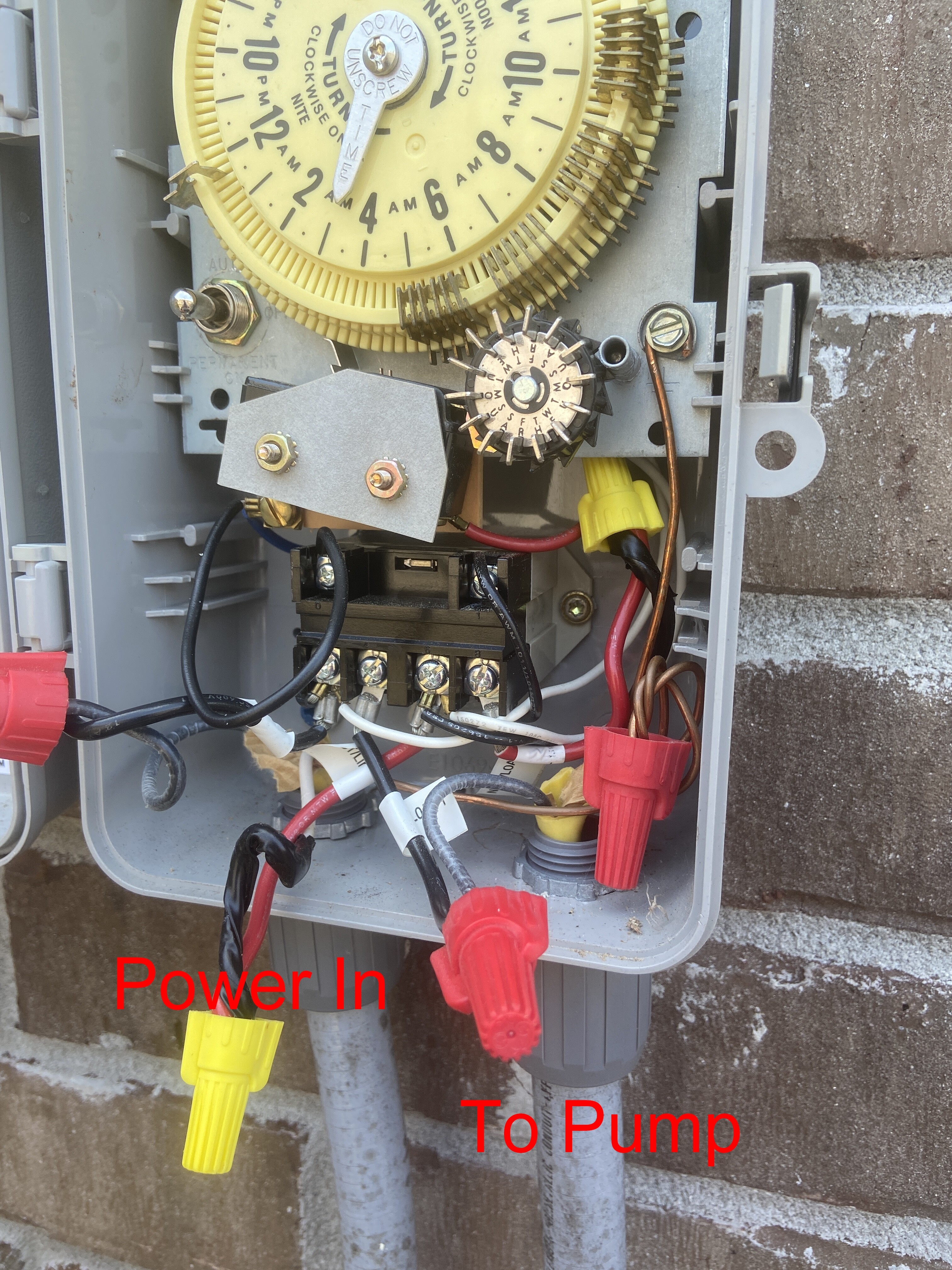
If I run power to the pump relay start, can I tap off where the power is connected at the pump relay start to power the Rachio also? Or do I need to go straight from the power box to the rachio? (thus adding an extra hole to that black box in the original picture).
You have to be careful to check that your pump is powered by 110V. Some are 220V and using the same voltage will fry both the Rachio supply & your new controller.
From the photos it does look like white (neutral) and black (hot) are the power wires, meaning it is possible that it was initially wired correctly and these are 110V lines. Black & Red pair would normally indicate 220V, but some electricians are lazy and use the wrong colors (so be SURE to verify).
You can use a cheap multimeter from a local home improvement store. Check across port 1 and 3 of the relay (LIVE voltage! so be careful).
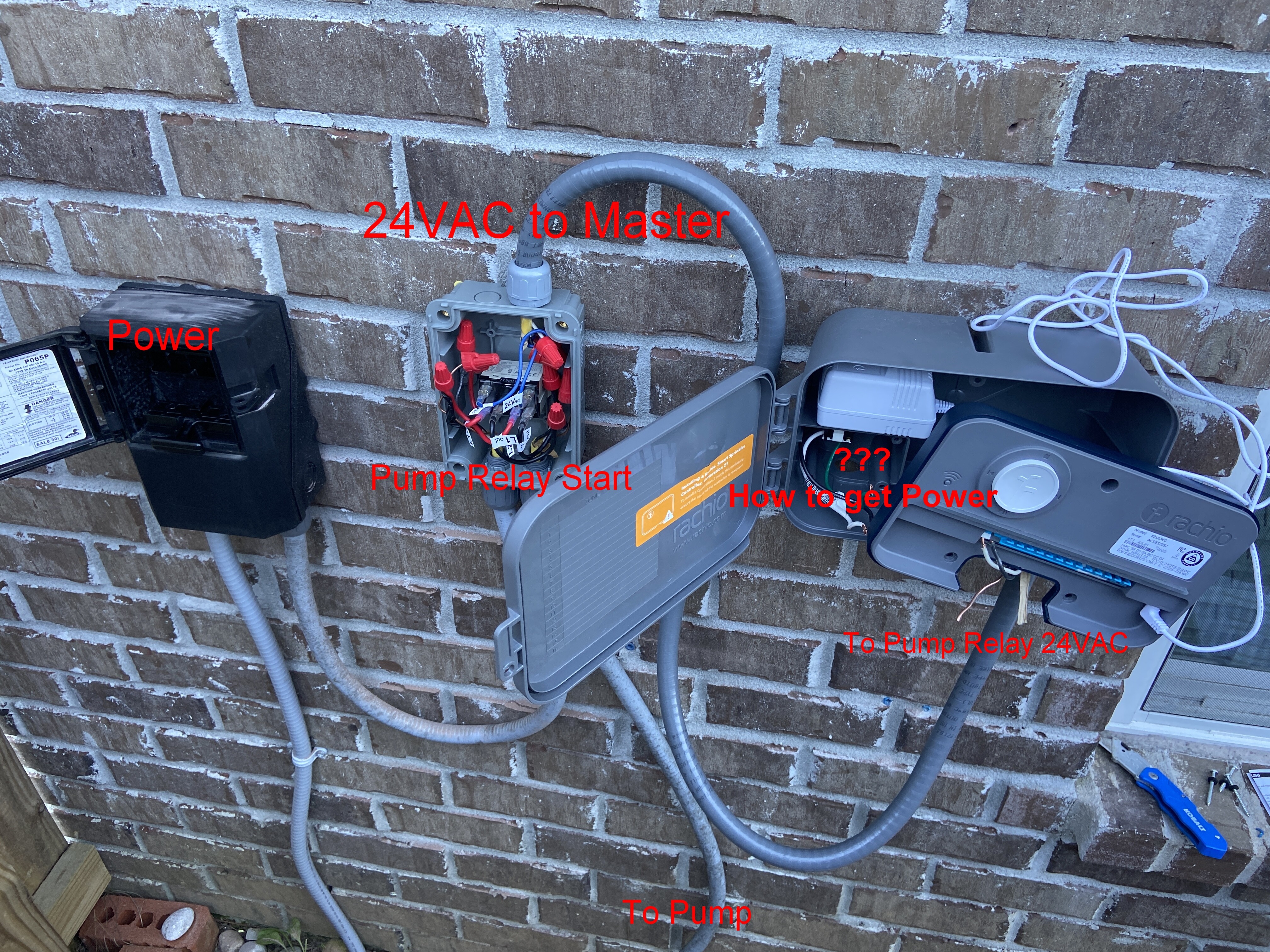
@Gene Thank you so much for all your help. I continued working on the project today and this is where I’m at (in the picture). Everything “seems” to be working right for right now with the indexing valves (I’ll change to individual at some other point).
The only thing I can’t figure out that I’m hesitant to try power up the outlet inside the Rachio Box. Right now, I’m just running an extension chord to the Rachio to make sure everything I’ve done so far is hooked up correctly and it looks like it. WiFi is good, “zones” are set.
Any ideas. I know you had mentioned to test for voltage for 110V and 220V on the pump. If it is 110, can I tap off those lines to the outlet inside the Rachio? Is it’s 220V do I need to hire an electrician to run another line? Is cutting off the Rachio power adapter and connecting an option for any of this? I feel like so close, just want this done haha.
Ideally you’d have neutral available in the power cable going to the pump. It is normally a white wire and you seem to have it, though I would not unconditionally trust that it is neutral and not just a lazy electrician back in the day using a wrong wire for a job.
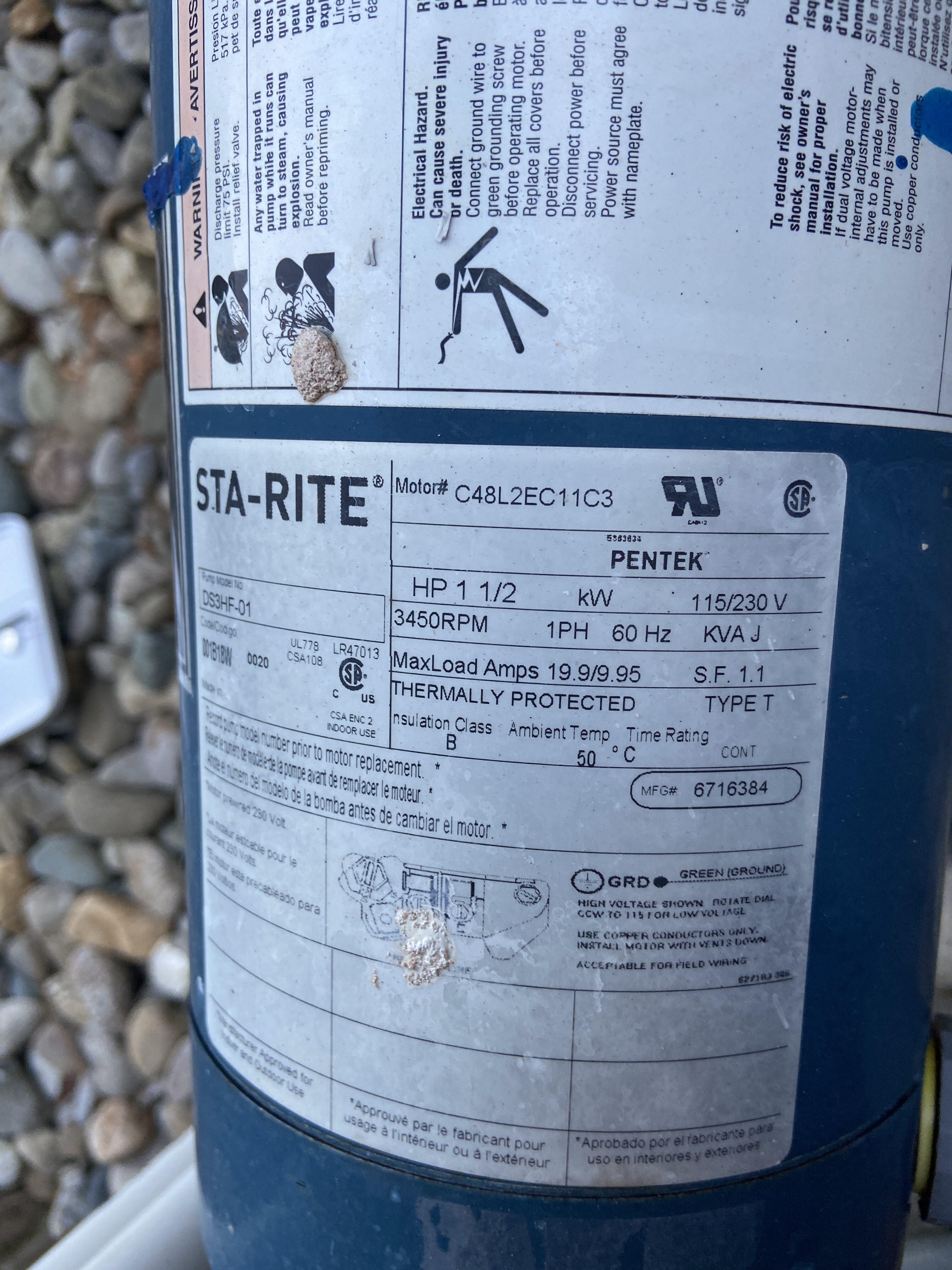
Take a photo of the pump label (if any), it may show what voltage it supports, if it’s a 110v only pump, you are safe to tap into and use existing wiring / power.
I’m assuming since it says 115/230V that I need to figure what it’s switched to? Thank you once again. I honestly would’ve paid somebody to do this, but people are backed up for months here.
Just get a cheap multimeter at your local home improvement store, you can get one with AC voltage measurement about $20.
Disconnect the isolator (what you have labeled as “Power” on your photo) and measure across the left / right terminals until you see a voltage. Some combinations may not show any voltage (if you measure across outputs, or between one input and an output for example), but simply try another combination until you find one that works. You’ll find four terminals, so try (1 and 3), (1 and 4), (2 and 3) and (2 and 4), you have 25% chance of any specific combination showing a voltage.
Alternatively, you can disconnect (red) input terminals from the relay and measuring voltage there, but it’s more dangerous since wires are free to move around.
I’m curious what your finished product looks like. I am having the same issue. I removed an old Intermatic but need to install a relay to power the well pump.