Small update 
3 Likes
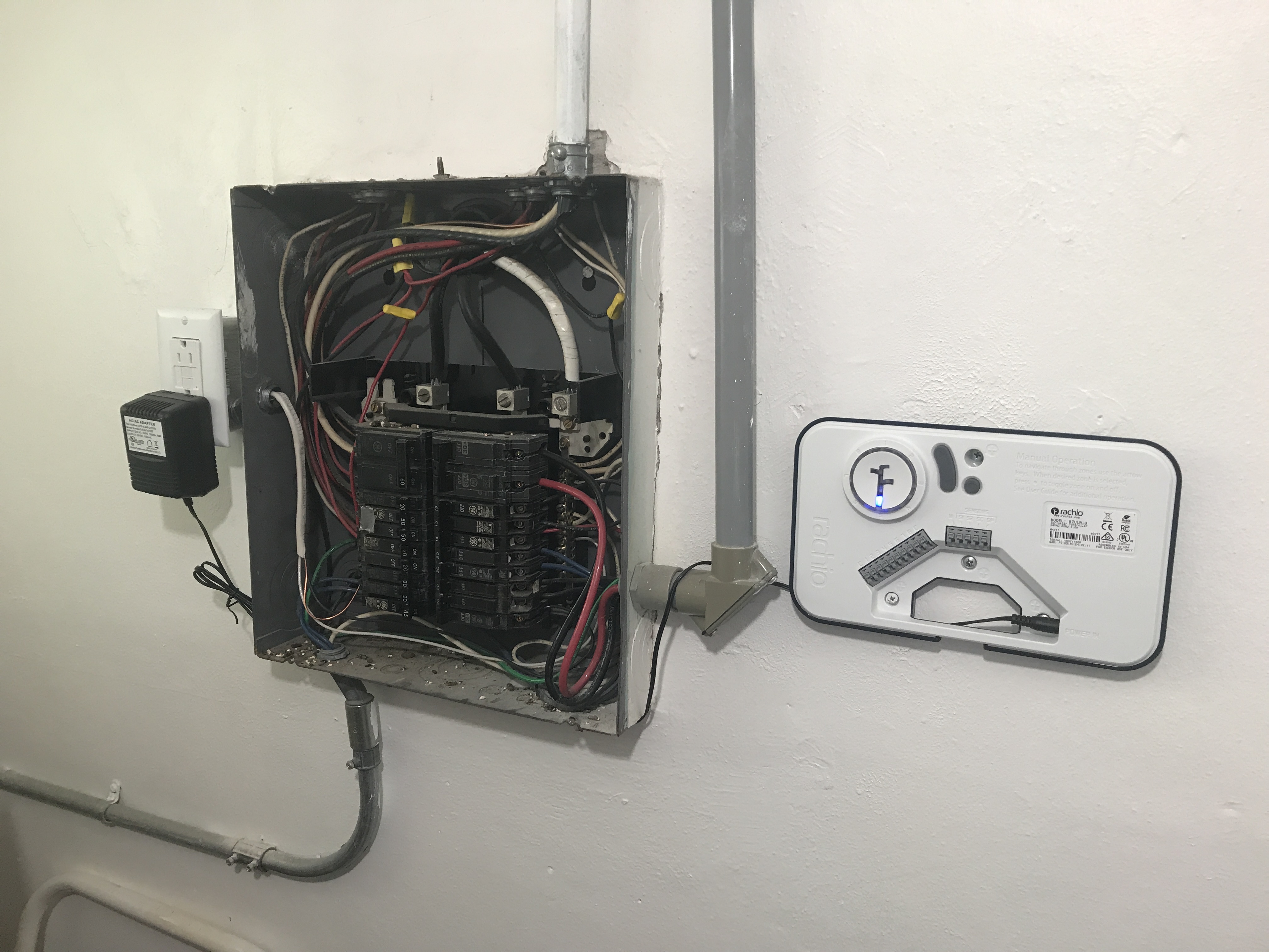
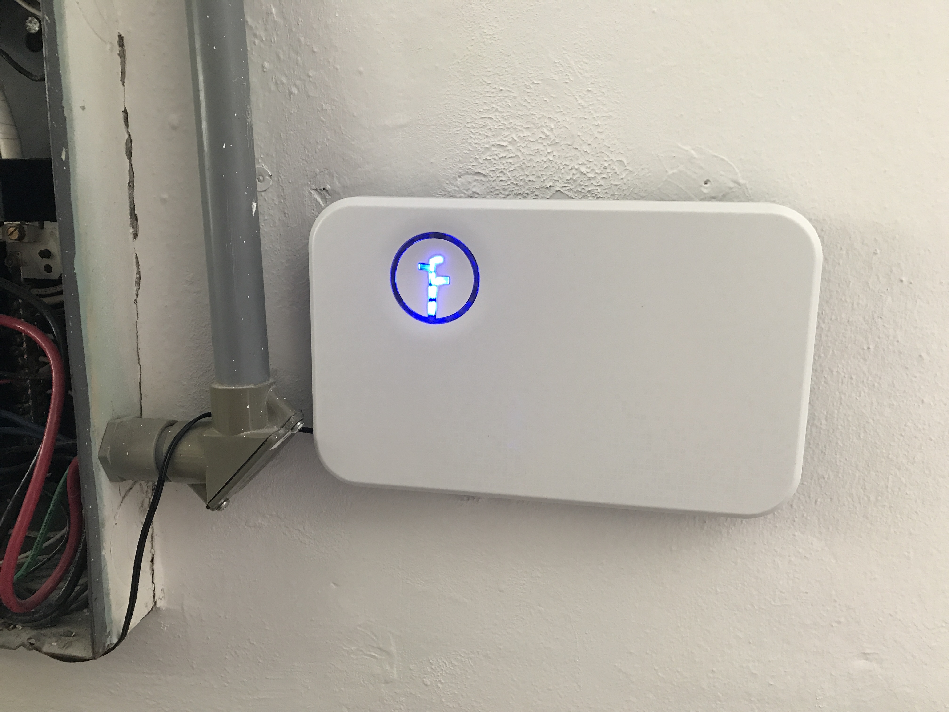
@rmadrid20 - progress! I’d go ahead and set up the Rachio unit as I only see light one lit.
Yes now that all my sprinkler heads are fixed (took me long time) and my rachio it’s mounted it’s time for the valves to be installed
1 Like
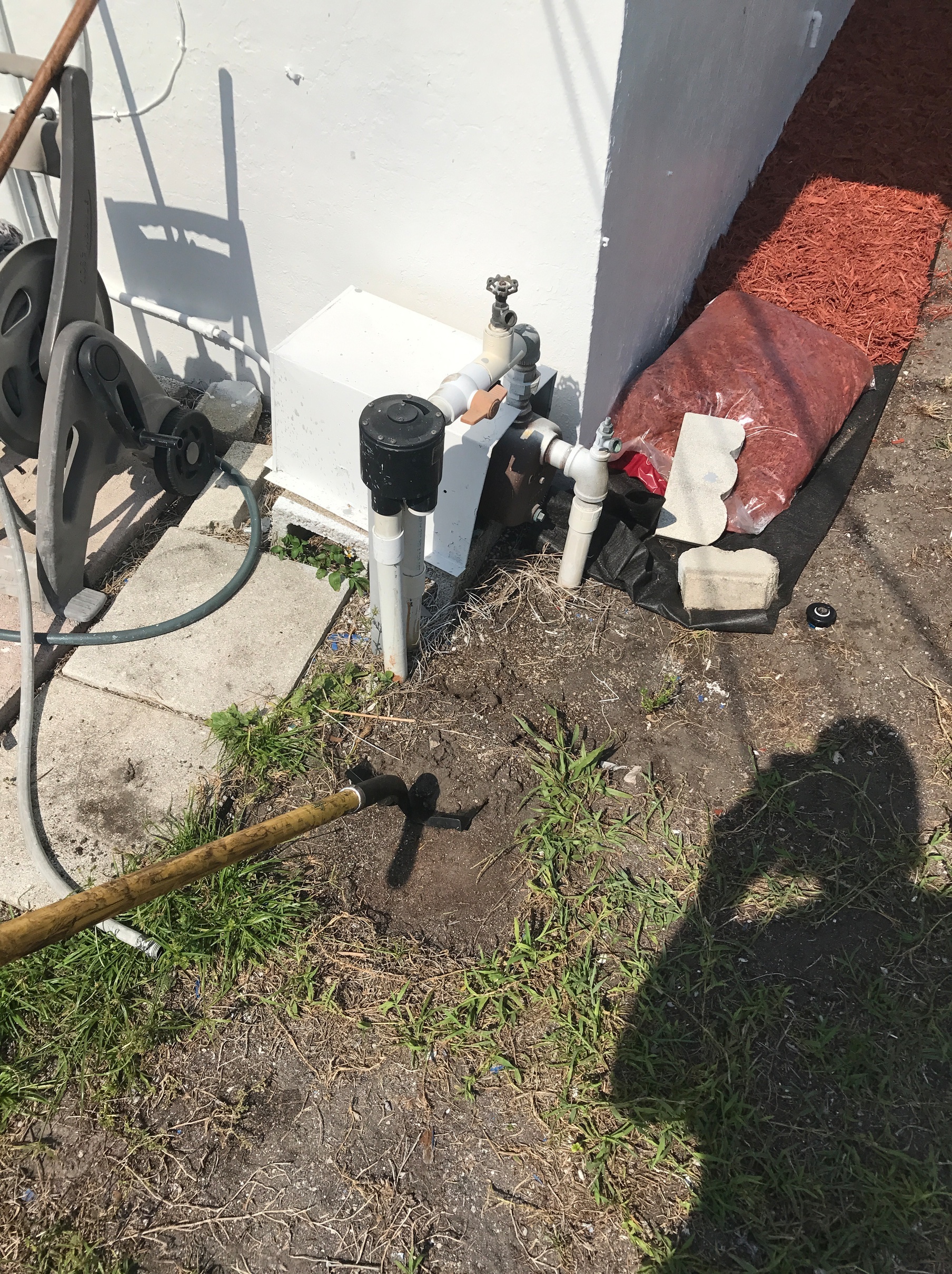
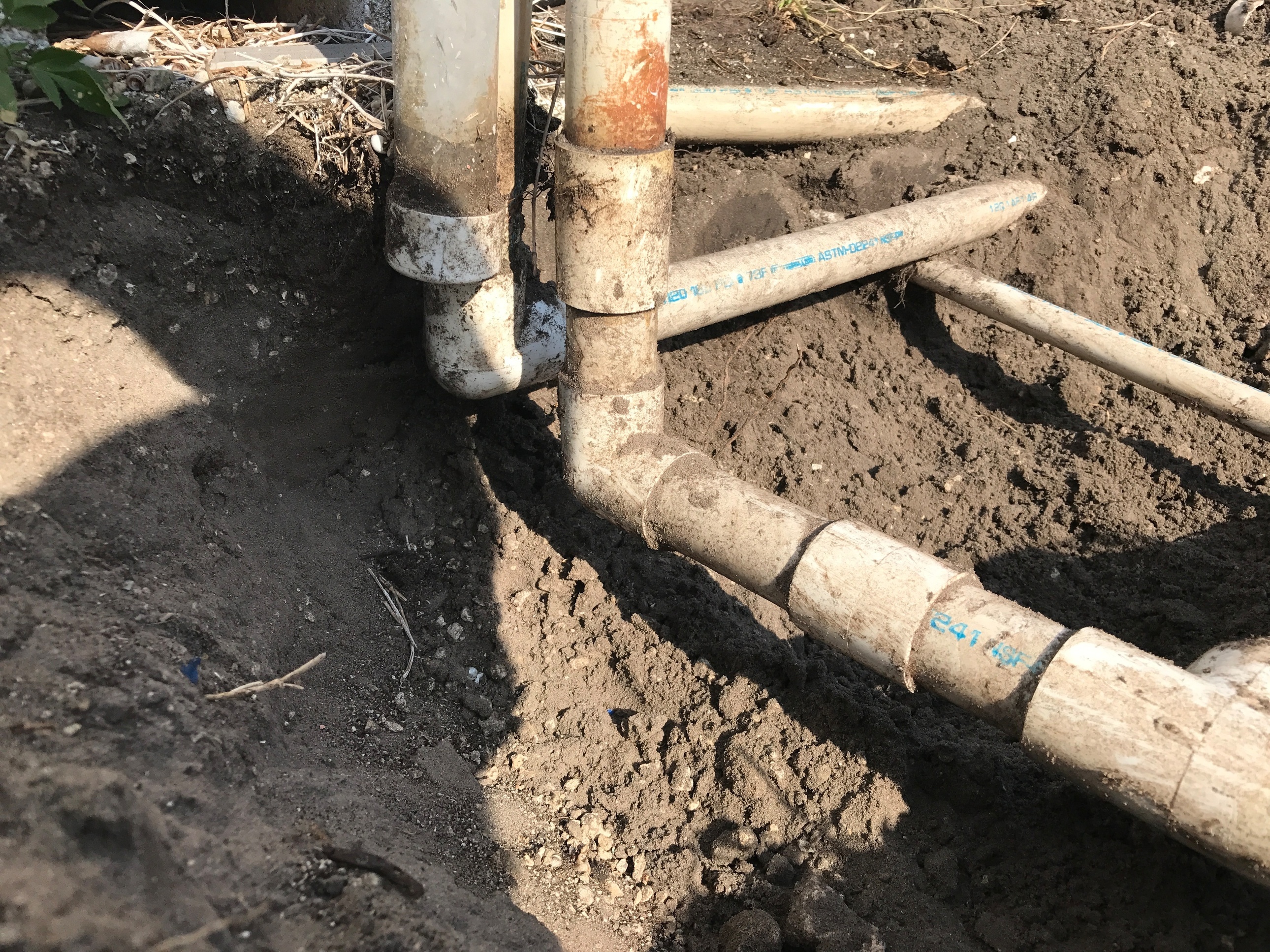
As you can see, the first pipe from the left it’s the main feeding the pump, the second one to the right (big pipe) its one zone and the last big pipe it’s a second Zone that splits in 2. I’m wonder if I can create a third zone since I have a 3 zone valve?
1 Like
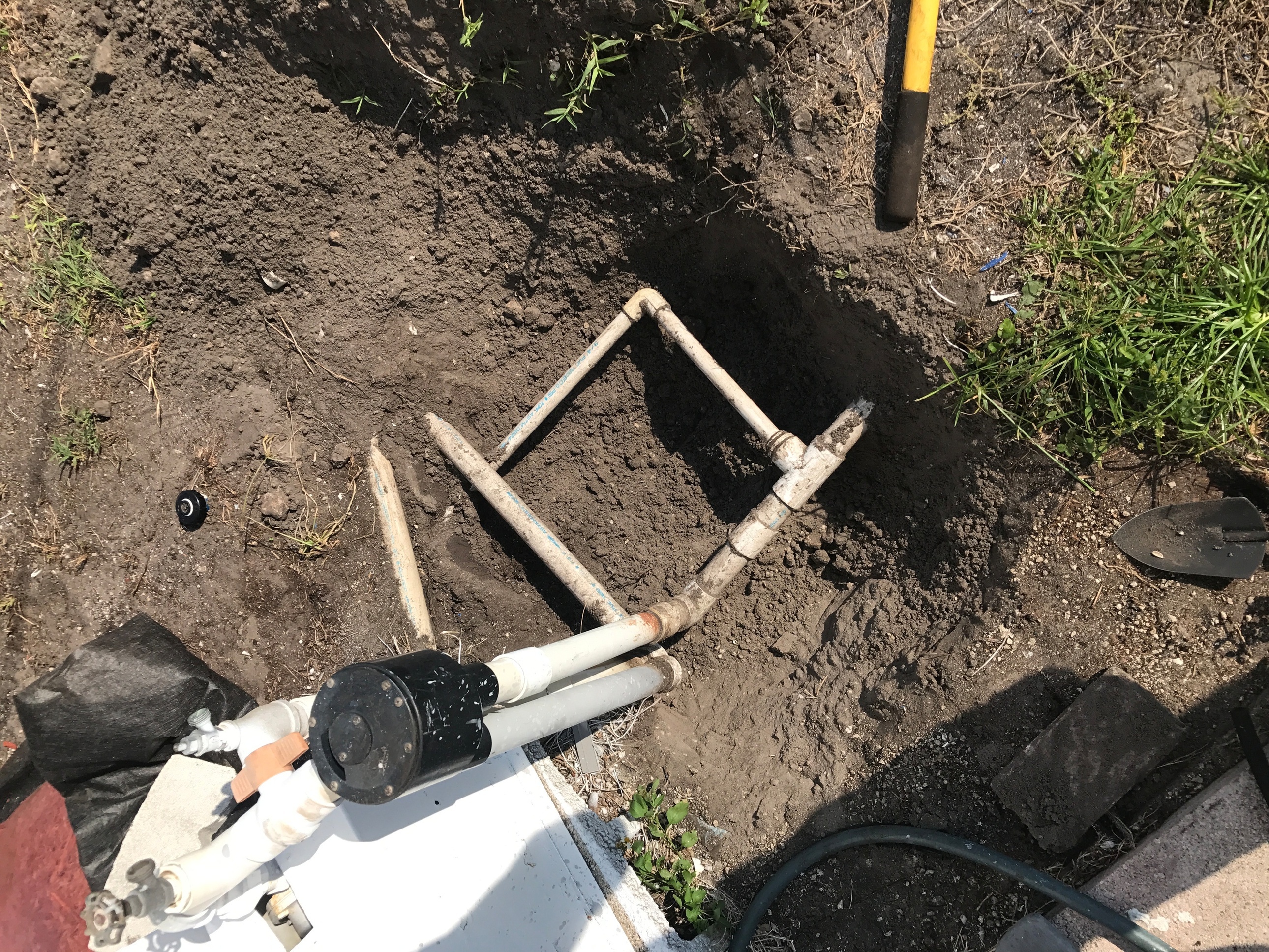
@rmadrid20 - I thought there were three zones on that indexing valve. The water from the pump comes in at the top of the indexing valve - correct? And the I see three lines going out, one of which isn’t completely uncovered yet, the one at the bottom of the picture.
Yes the water come from the top you are correct then only two zones are working as you can see in the pic but for some odd reason one zone it’s split in 2 so what I’m going to do is go back and have 3 zones
Way to go! Great progress 
I think that split off zone is actually feeding the lonely sprinkler head you see on the picture, not sure if it really deserves a full separate zone.
I’m glad you’ve uncovered that one of your zones was dead, you where paying for at least half hour of running a pump for nothing, your ROI just got closer
If you ever think of planting anything near the house, you may want to look into drip irrigation and hook that up as your 3rd zone.
Cheers,
Gene
1 Like
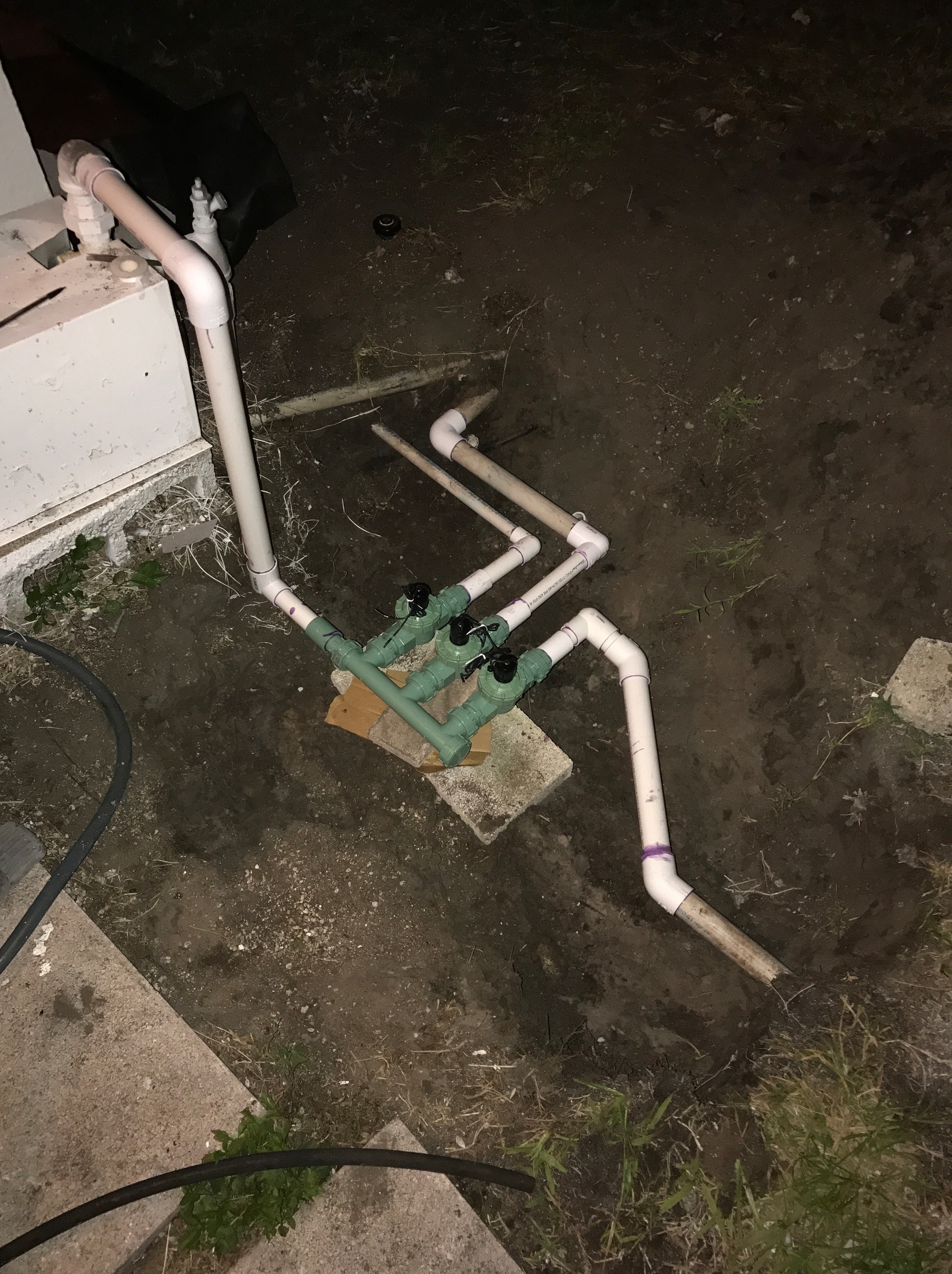
That 3rd zone it’s covering 6 sprinklers on the south side of the house and this is the progress she far, I’m so tired but I’m close to finish, I think the fuse box and the relay is tomorrow and we will be done guys
3 Likes
@rmadrid20 - looks great! Hopefully this will help/encourage others to de-install their indexing valve system. I don’t expect the disconnect and the pump relay to give you any fits after what you’ve done so far.
1 Like
Don’t think so either, I’ll follow the muck up you sent me, if I have any question you’ll se a post, any ways I’ll keep you updated with pics
1 Like
Very well done! Looks great
Which valve box did you buy, I really like yours @Gene
1 Like
I guess I’m not the only one burning the midnight oil
I’ve used a Valve base from Orbit (link) with a “standard” Valve Box (link). Keep in mind that a standard box will likely be too tall for the depth of your valves. Most stores will carry other valve boxes that may fit the Orbit base but are not as tall, such as this one from Lowes (link).
I’ve also bought some loose stone (as cheap as I could find) to put underneath to aid drainage (and keep the vales hopefully dry).
Cheers,
Gene
P.S. If you go back and look at my install (link), you will notice that originally I was planning on using a smaller box (first two pictures), but had to switch to a larger box at the end (next to the last picture).
1 Like
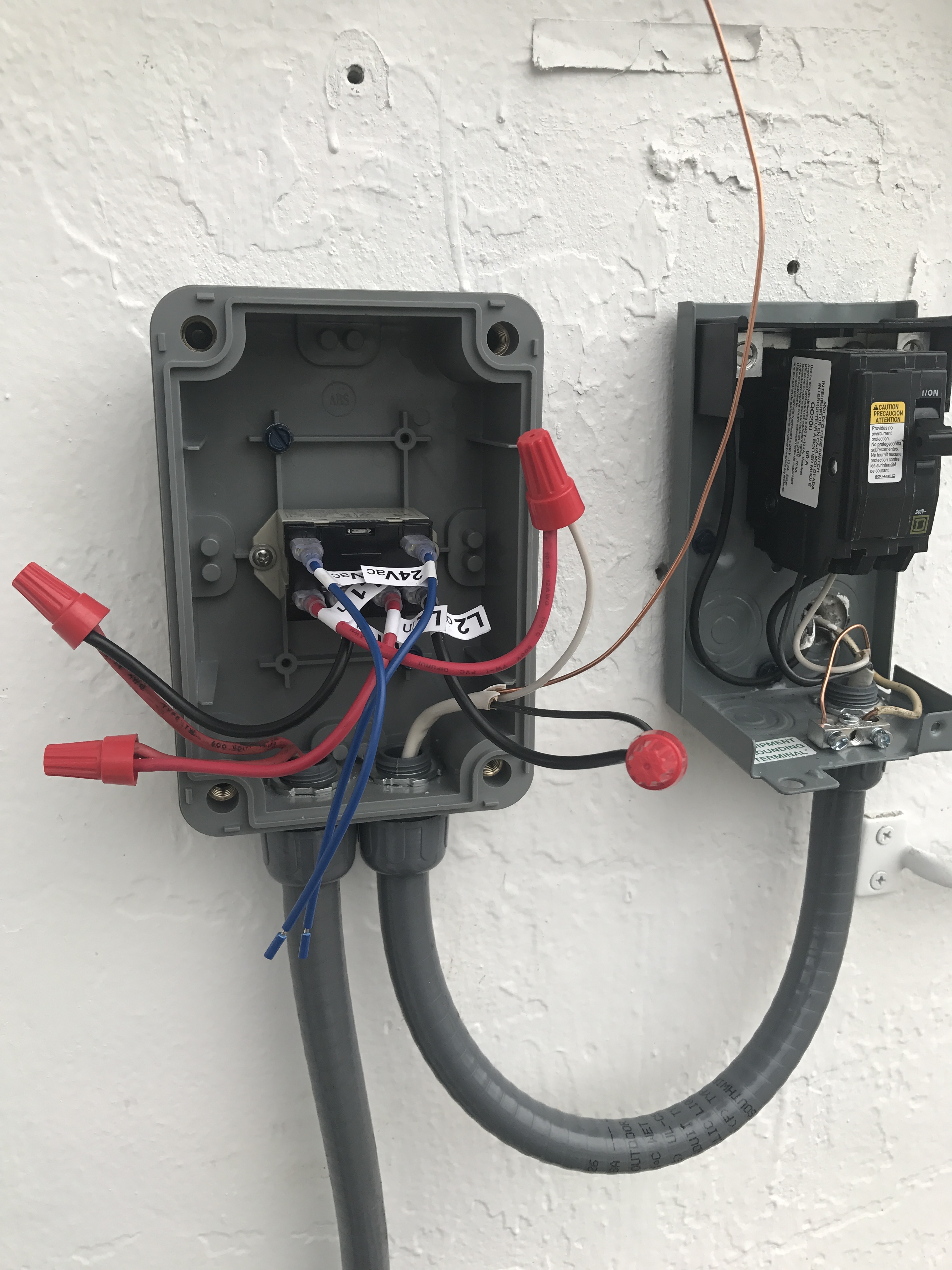
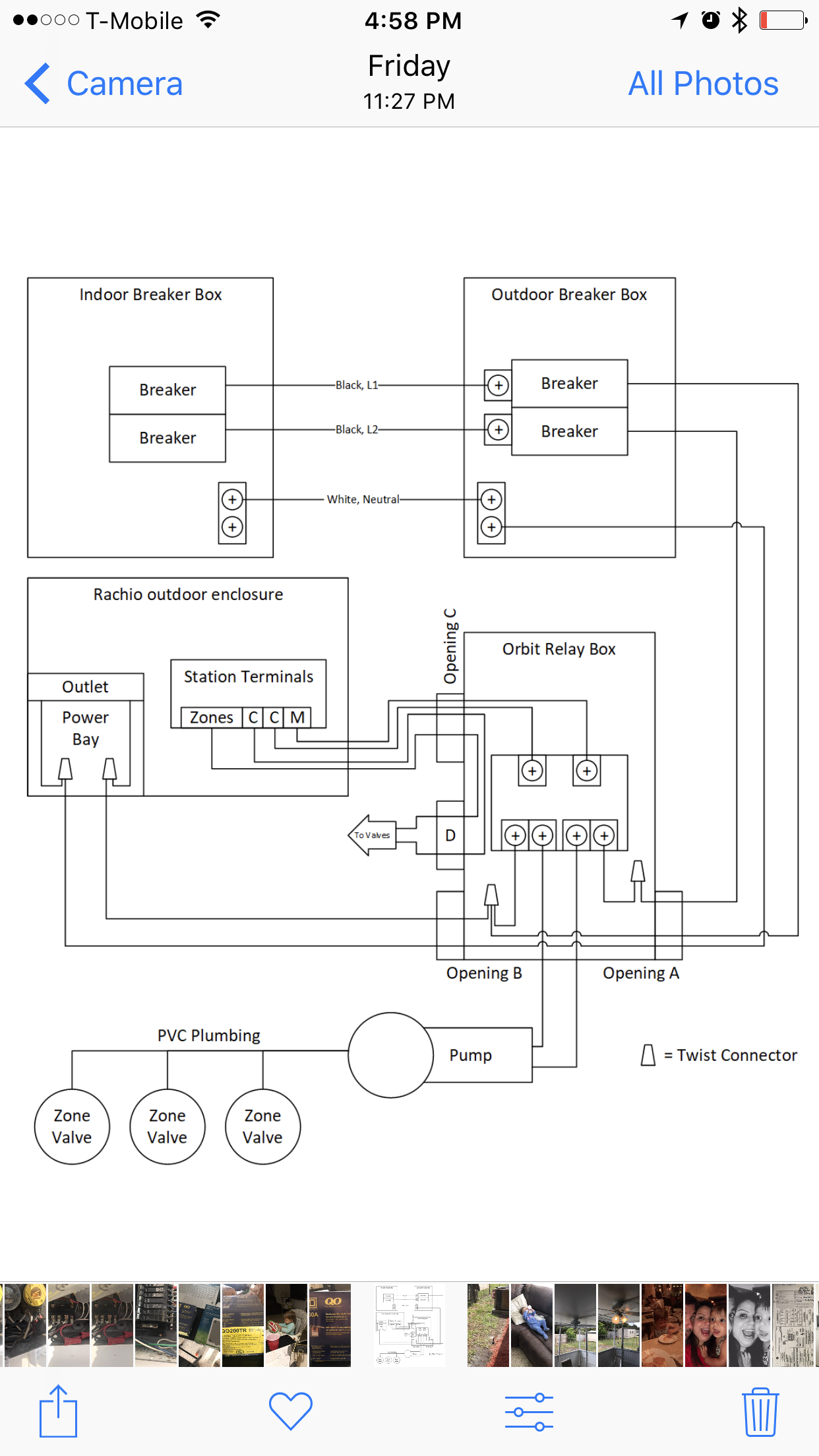
@rmadrid20 - on the pump start relay I think the L1 In and L2 In wires are both red. Those should connect to the two wires coming from the disconnect. I think one of the wires coming from the disconnect is actually connected to the L2 Out wire. The L1 Out and L2 Out wires are both black and I think they should be connected to the wires going to the pump.
The 24Vac blue wires will be connected to the Rachio M/P and C(ommon) ports.
This is based on visual observation, as I don’t have the instruction manual for the pump start relay.
1 Like
I’m following this pic and you see the 2 center lines are going to the pump if I’m wrong I’ll switch them
You are on a roll 
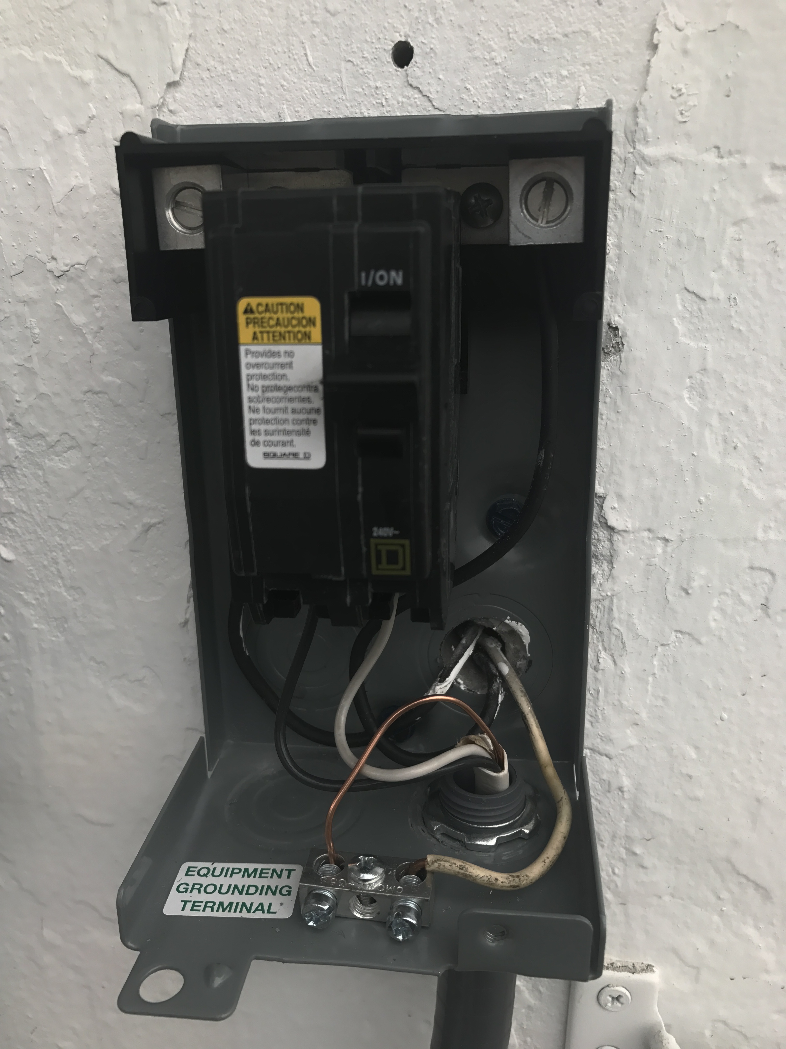
One thing I would like to check is the gauge of the wire connecting your outdoor breaker with the relay box. Look for “AWG” with a number next to it on the cable, ideally it should be AWG #14 or less (such as #12).
Also, considering that you are not using a neutral / ground wire within the relay box itself. I would trim / cut it off as to prevent accidental shorting with something else. Don’t worry about the red/black wire colors within the relay box, what you have now should work (relay doesn’t care what is output and what is input with AC voltage).
@rmadrid20 - as that is @Gene 's drawing I’ll let him opine. I’m a KISS guy, I match “in” with “in” and “out” with “out”. As someone might come behind you on this effort, they might be surprised with “hot” power on the “out” connection. The instructions that I saw said to connect incoming power to the “in” connections and the pump to the “out” connections. And +1 on Gene’s comments regarding trimming the neutral/ground wire and the wire size.
1 Like
I agree with @DLane, if you can make the change now, it’s better be safe than sorry. The reason it appears on the drawing as such is because it was easier to draw that way. The way you have it (matching the drawing) will work without a problem, but as @DLane mentioned, may cause confusion in the future.
1 Like
Gentleman I want to inform you both @Gene and @DLane that ITS WORKING and I’m freaking happy, THANK YOU SO MUCH for the time you guys took answering all my questions.
Need to clean the area and attach some cables to the wall but it’s working, any special settings in the app I should know?
THANKS!!!
2 Likes