Intermatic Mechanical Timer Replace

What software have you used? The valve (with red dot) is not strictly necessary, but will not hurt if it fits.
Also the valve on the left is shown backwards, the valve part (that has solenoid attached) should always be on the pressure side (on the pipe connected to the pump) not the drain (pipe going into the ground).

Yeah that’s a manipulated image, the backward one it’s just to get the idea of what to buy. The rest is on illustrator lol.

Yeah the ball will be moved or taken out if it doesn’t fit. At home depot now buying to dry fit

1 Like

Don’t mind tape, but this is looking like it’s gonna work fine. Now to get a 1” female adapter into the siphon.

Then figure out the electrical part, then to wing it.

1 Like

Is it possible to install the siphons before the controller and pump relay? Like will it still work? relay arriving later this week. But I wanted to install the pipes and turn on timer after it dries and make sure what goes through fine.

Sure. You can either drive the valves from Rachio (powered by extension cord) without installing it permanently, while running the pump with the old timer, or …, simply turn the valve(s) on manually by turning the solenoids clockwise to turn on, CCW to turn them back off.

1 Like

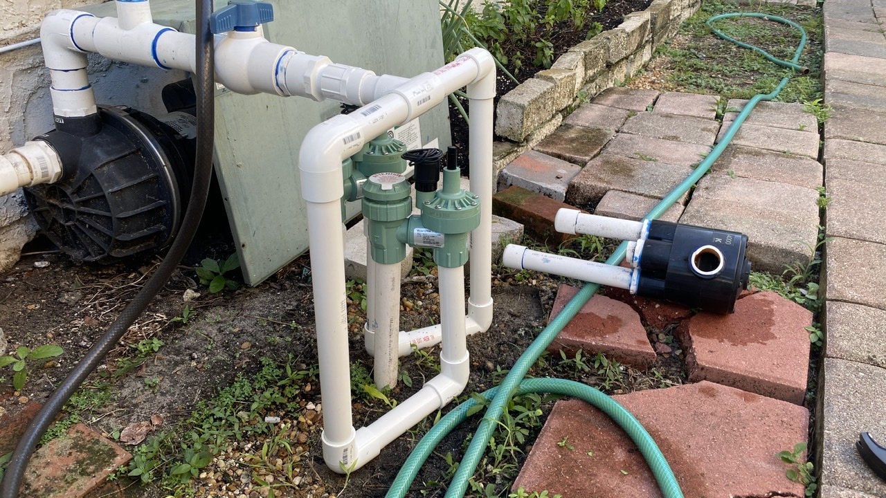
How does this dry fitting look? Also the parts that screw, do they go all the way in? How hard should I torque?

1 Like

Looks good, though the valve on the second picture does not look to sit alighted with the pipe. This is probably due to this being a dry fit, but make sure there is not much of a gap between the valve inlet opening and the pipe. Glue can’t fix a large gap.

Do not over tighten the screw fittings. You can find a thread sealant in a home improvement sore. Something like this:

https://www.lowes.com/pd/Oatey-Great-White-Sealant/4750813

Make sure to look for one compatible with PVC

1 Like

I actually got the thread tape for the thread, and yeah it doesn’t even have the adapter to go on the pipe, just threw it in there to measure. That’s why.

Got the relay today, gonna need wires, do you know which I have to get? I assumed they sold one for the sprinkler controller?

Probably mount the controller near timer box since that’s were ima install the relay.

Careful not to go overboard with the thread tape, too much and you may crack the valve / pipe.
Irrigation wire is sold by the foot at home depot / lowes, something like this (link).

These are available in the electrical department, just ask an associate to cut some for you (tell them you need 3 or 4 conduit irrigation wire, ~15ft).

I recommend you run separate wire to the relay (you need 2 conductors or more) and the valves (you’d need 3 conductors or more). The wire I’ve linked to has 4 conductors,

1 Like

So i’m buying 2x 4 Conductor Wires , each 1
15 ft

No, one run will likely be enough, simply cut it into two peaces where it makes the most sense.
You may not require the 15 ft, simply figure out how much you need for the run to the relay and how much for the run to the valves. For example if it is 3 ft to the relay and 5 ft to the valves, you may get away with 10 ft of wire (3ft + 5ft + margin). 15ft was my over-approximation based on what I saw.

1 Like

Just to be clear, run them from controller is what you’re saying? Controller to relay and controller to valves.

yes

1 Like

@Gene, I’m laughing at this thread…would have been more efficient to fly over and just do it! You are the man btw…cool of you to help him through ever step.

2 Likes

Yeah I appreciate his help, without him would of took a lot more confidence but him confirming for me makes it easier.

Yeah he’s 10-15 mins away from me lol

2 Likes

And take away from your pride of having done everything yourself? Great work by the way, I don’t mind all of the questions, now we can use this thread as a good tutorial for others. :+1:

3 Likes

yeah will make wiring diagram later to post to see if i got it right and will get some conduit just because later when I get an adapter for pvc today after work

Now work on wiring diagram and to wait 24 hour to test for leaks and flow. Bought the wires and conduit.

Conduit from Relay in Mechanical timer box, to the rachio. Going to also run sprinklers cables through there. Make another hole in the mechanical timer box to run cables to sprinkler valves.

Thoughts?

Gonna see how people routed cables from valve to box neatly, not that I mind wires free but I like things clean.

Wiring diagram coming soon

1 Like

Alright here it is. I attached my mechanical box, to show how its connected. As well as the diagram I got off this forum somewhere that I based some of my decisions, then compared to my actual wiring right now.

If you look at the mechanical box, the wires coming out of the right side is from the breaker box and the bottom goes to pump.

Let me know what you think

You found one of my old drawings :wink:

Do not ground your pump to the rachio controller, in your old timer it was done for simplicity, but the purpose of the green wire on the second photo is to connect to the white wire attached to the same nut. Because your breaker box is the first one downline from the meter, your Neutral (white) lines and ground (green) lines are interconnected there, thus it is possible to use a white wire (like they’ve done) to ground the pump. Fix: G1 terminal of the pump should be connected to W1 terminal of the breaker.

W1 and W2 terminals do not need to be tied together (no need for a wire nut), simply run the (white) line from W2 terminal to W terminal on your Rachio controller. Green (G) terminal can be left disconnected on the rachio controller (just cap it or connect it to the W line), since the power supply does not use it.

Otherwise you’ve got it, good job :slight_smile: