Zone wiring

Hello Everyone. I converted from a rainbird controller to rachio about 3 years ago and everything has worked great. Well now zones 4-7 won’t turn on and I’m getting a 0 ohm reading from the controller. This started after we had our roof replaced so trying to figure out this wiring scenario. I think* the red wire is the culprit out in the yard but I’m also trying to figure out the red wiring at the controller. Could anyone give any advice? As you can see the red wire from each strand is connected together. It appears the white common wire only goes to zones 1-3. Could the red wire be the common wire for zones 4-7? Note, this was original wiring from when we had the rainbird.

Thanks again for any feedback.

@CourtneyG - It does appear that the red wire in the bundles may be the common wire. I’d test the resistance between zone 4 (or 5, 6 or 7) and the red wire in their bundle. I don’t see where the red wires are joined to the white common wire - it could be out in the yard. If you know where the valve box is for one of the problem zones, I’d look at the wire colors in the box.

Also, I presume that the valves work when manually activated in the valve box?

I dug up around the valves in the yard and the only white wire out there is from the bundle that is going to the zones.

Yes, valves work manually. If the red wire is in fact the common wire for zones 4-7, can I just connect that red wire to the other common port on the controller?

All common (C) connectors are tied together internal to the Rachio, so any will work.

So I went back to basics to try teoubleshooting a wire break so I connected only zone 4 to test out first. When I run the zone, water comes out some opening where the well pump is located, assuming it’s some kind of back flow? What does this mean?

I have never had a well, so do not know. It seems like if water is coming out while a zone is running, that might be a problem (but I could be wrong). Usually backflow or drains might put out water right after turning off the zones.

First, I’m a bit new at this, but I’m a nuclear engineer and I understand basic electricity. I’ve also successfully done some troubleshooting with my own irrigation system. Basically, I believe you need to figure out whether the red wires are indeed common, and if so, connect them directly via jumper to another C terminal to improve the common connection. Then troubleshoot the bundle 4 wires to determine where the problem is.

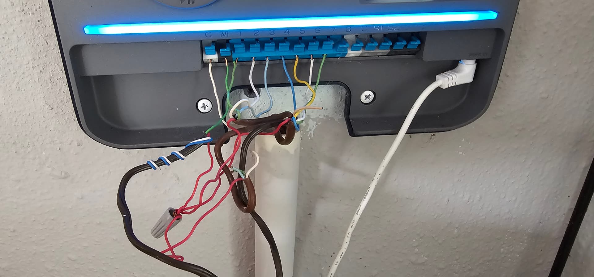
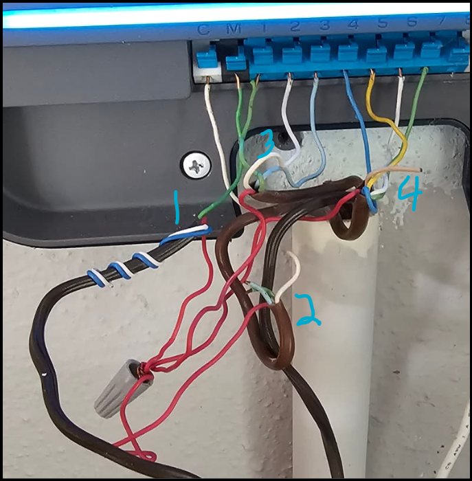
Looking at the wiring, I see 4 bundles - if you number them from left to right in the photo, you see that
all four bundles have a red wire connected to a wire nut - this makes it pretty likely that red is common.

Bundle 1 - red to 4 connection wire nut, green to zone 1 valve
I’m thinking that if zone 1 works, then red must be common, and all 4 reds must also be connected to the white wire in bundle 2 somewhere out in the yard

Bundle 2 - red to 4 connection wire nut, white to common, green and blue unused
This bundle connects to no valve, but to white common and red (that seems to be common) - it could be this bundle that connects red and white together somewhere out in the yard

Bundle 3 - red to 4 connection wire nut, green pump motor, white zone 2, green zone 3
SInce you say that zones 1, 2, and 3 work, the white common wire must be common for valves/zones 1, 2, and 3

Bundle 4 - red to 4 connection wire nut, blue zone 4, yellow zone 5, white zone 6, and green zone 7
All four of these don’t work, so it’s logical to conclude the problem is in this bundle of wires, or the problem is in one of the connections out at the 4 valves.

I would disconnect wires and check resistance from white (common from bundle 2) to the bundle of reds. It should be zero if the commons are properly tied together somewhere out there. If it’s a few ohms that’s probably OK, but it shouldn’t be in the tens of ohms. Note that if bundle 3 serves only to remotely connect white and red together, then a shorter path to this is to run a white jumper from the 4 reds wirenut up to another of the C common terminals.

Now check the resistance for zones 4-7 - they should all be in the 20 - 60 ohm range, and since they’re probably the same model of solenoid, they should all be pretty close to each other in reading. If one or more have extremely high resistance, or infinite resistance, then there is a break in that wire that goes to those valve(s). If you can locate the three valves, you can do a couple of things: first, you can confirm that the red wire is indeed common for those three - in other words, at valve 4, the blue wire from the bundle should be connected to one of the black solenoid wires, and the red wire should be connected to the other AND the red wire should also be connected to the red wire in the bundle that runs to the next valve. To figure out whether the whole bundle has been severed, you can temporarily connect the wires going into one of the valve boxes together. It might be that the red wire is severed, and you could repurpose the (beige unused) wire in it’s place. At the very least, out at the valve you can connect two or more wires together temporarily, then see if the resistance back at the controller is zero for those connected together. If that’s the case, then for each pair that reads zero back at the controller, the two wires are intact out to that box.

Sorry for the length of this post, but I was thinking it through as I went. Hope it helps!

Thank you so much for the reply and assistance :grinning: So “bundle 1”, the green wire is going to the M port, hard to tell by pic. Bundle 3 goes to zones 1-3 with red common bundled.

So out in the yard they did a horrible jon daisy chaining the red common to the valves and the wires looked like there were some nicks. I took the red from the bundle 4 and connected to the solenoid for zone 5, and still not turning on. I’m getting still getting 0 ohms atthe controller which I find hard to believe that just the red wire would be cut in the bundle somewhere in the yard and none of the rest. I get good volts when I run the zone so I would think if it’s a cut line, I wouldn’t get a good volt reading or ohms, unless I am not thinking correctly.

With 0 ohms on zones, it is likely a broken or disconnected wire OR you have the wrong wire.

@CourtneyG - just to be clear. When you are getting 0 ohm, is it truly 0 ohms/no resistance which would indicate a direct short thus not going through the solenoid? Or is it really infinite ohms which would indicate a open circuit? On my analog multimeter 0 ohms is far right on the scale and infinite is far left on the scale.

Oops, I went the wrong way. Thank you for the correction @DLane!

Soo finally found the broken wire in the yard and repaired, or so I thought. Rachio is giving me an overcurrent of 548 on just 1 of the zones. Any ideas?

@CourtneyG - a short in the solenoid for that zone. Have you tried swapping solenoids with one that doesn’t error out? Or replacing it?

Thank you again-bad solenoid! What are the odds a bad solenoid plus a cut line in the yard😀

Curious for other’s benefits, how did you find the broken wire?