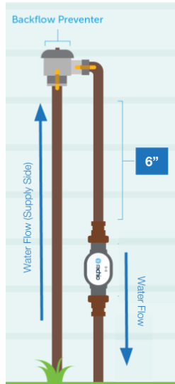
The illustration shows the flowmeter installation on the intake side of the backflow preventer. Text says it should be installed between the valves and the bfp.
Scroll down on this page and find image showing the side of the house.
The illustration shows the flowmeter installation on the intake side of the backflow preventer. Text says it should be installed between the valves and the bfp.
Scroll down on this page and find image showing the side of the house.
You are correct. Flow meter should be on the downstream side of the backflow. The cartoon illustration in your link is incorrect. In fairness, that pictorial is on the sales page and not meant as an installation guideline, but they probably should match. @franz @laura.bauman
Sales Page:

Installation Guide:
Good eye friends!! Will send this to the design powers that be for updating