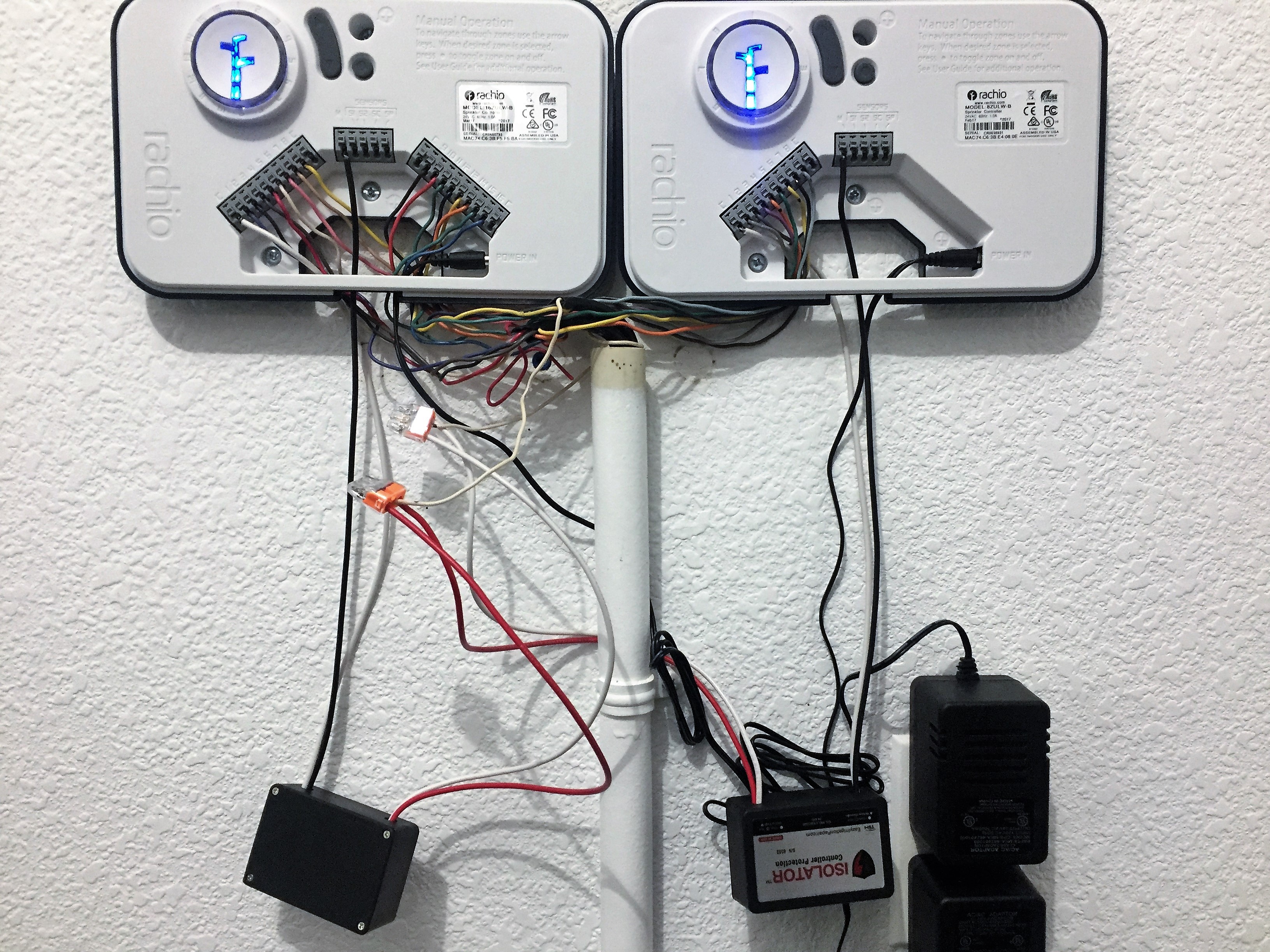
Just installed two controllers with the additional TSM isolators.
My old controller had a Master Valve connection. Being that I have two controllers and one Master Valve connection, have I wired this correctly?
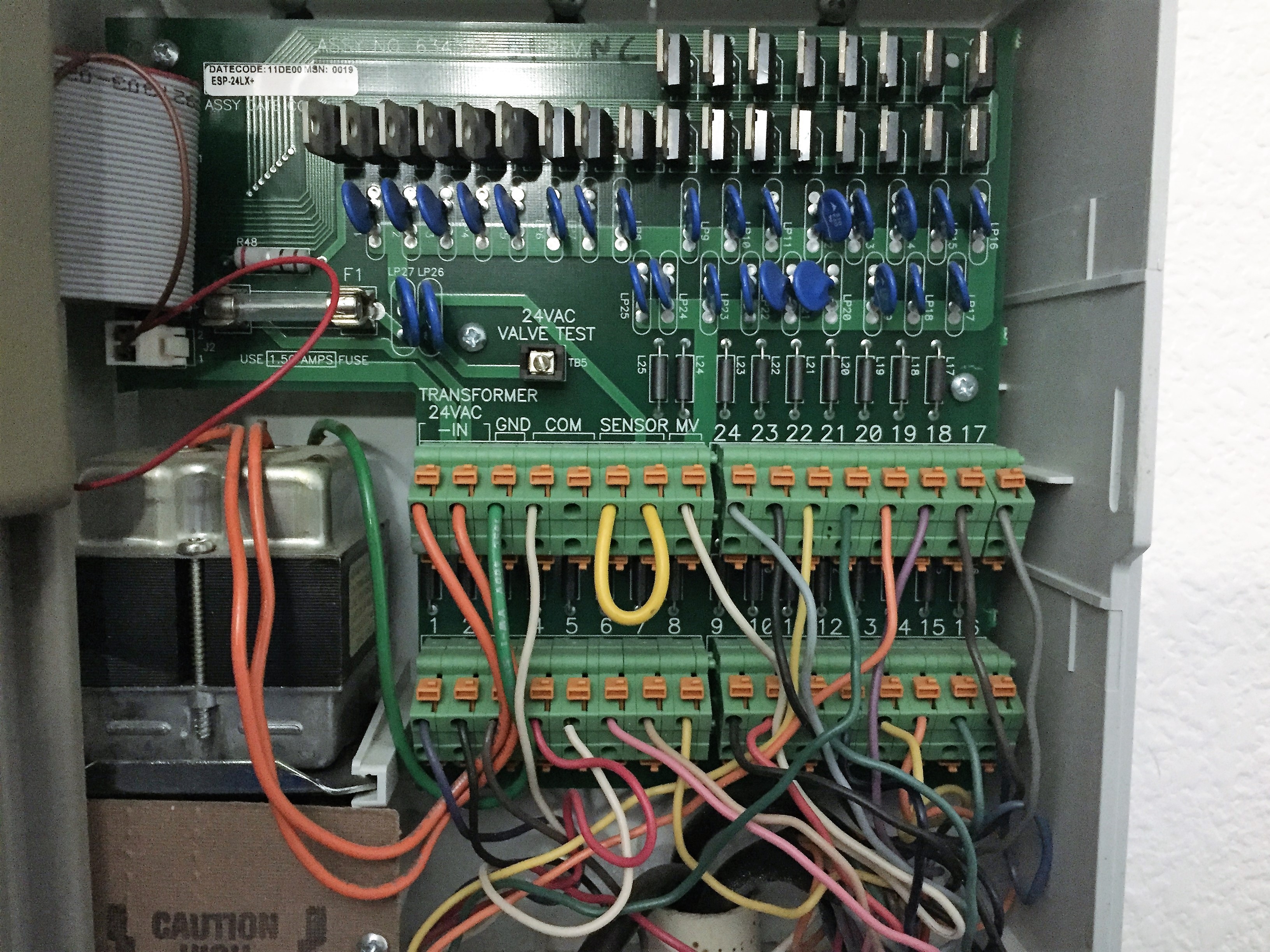
Old Controller
When I manually turn any of the sprinkler zones on, they wont start. I have ensured that the water main to the system is one and verified that water leaks out the weep valve.
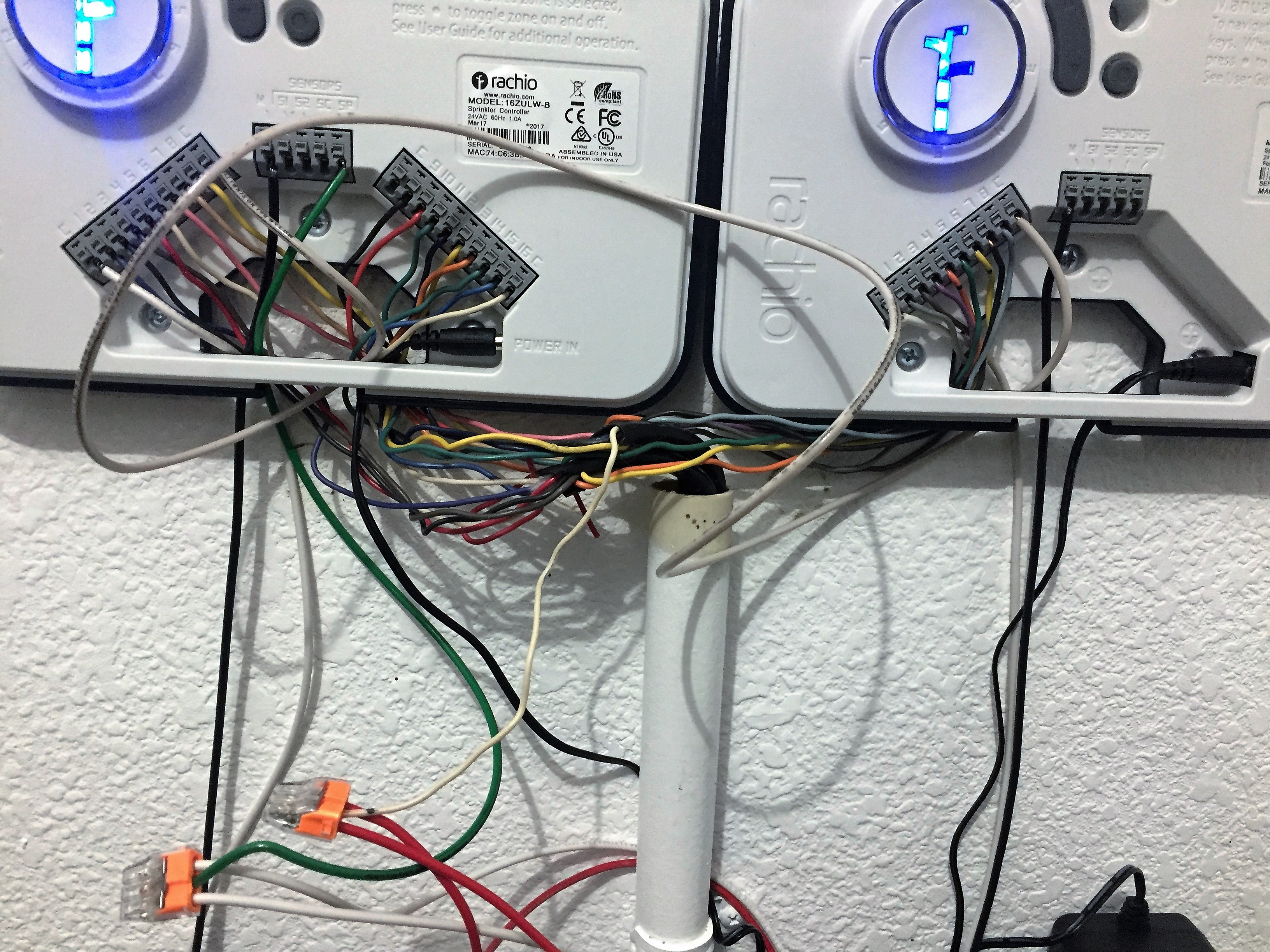
From a quick look, you don’t have any commons connected to anything other than your opto isolators, so none of your valves should work (much less master valve).
On your picture it is really hard to differentiate between your common wire (connected to COM) and your master valve wire (connected to MV). Seems you’ve connected both of them to your opto isolator outputs which will not do you any good.
I would wait until Rachio support team looks over my advice, but here is what I recommend:
Find your common wire, probably one of those connected to your opto isolators
Connect it to any C terminal of Rachio on the left
Run a new wire from any available C terminal of Left controller to any available C terminal of Right controller.
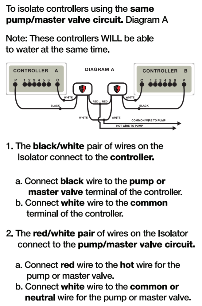
Connect the white sides of isolator outputs to SC terminal of either Rachio (though right one may be best due to reduced load)
Connect the red sides of isolator outputs to your master valve line (which may already be connected)
In the future if you wish to get rid of isolators, you should be able to get a 24VAC 2 Amp supply and run both of your Rachios off of one supply (theoretically you can do it off of 1AMP supply you already have, but you need to make sure you are not running 2 zones at the same time). If you do this you could avoid the need for isolators and simply connect your master valve line to both of the M terminals (using something like the 3 way connectors you already have).
You can use an ohm meter to find your common line (resistance measurement between common and any of the other zones will be about half compared to resistance measurement between master valve and any other zone).
You could also try connecting wires to C terminal and trying one of the zones. In case you connected master valve line, it will probably activate 2 valves (master and what ever zone you are controlling). Otherwise if you got the common, it will just activate the zone you are trying to run (master valve will remain deactivated).
Your correct, I only have the common connection running to the Isolators (white wire). I do have the prior (old unit) Common connection attached to the White Wire and the Master Pump (Old Unit) connected to the Red using a three way connection.
You will need to disconnect old unit white common wire from the white wires of the opto isolators and hook it up to any available C terminal of the controller on the left. Than you need to use a new wire to hook up left and right commons together (wire needs to connect from any available C terminal of one unit, to any available C terminal of the second unit). Finally you will need to run a new wire from any available SP terminal to the two white wires of your opto isolator. Don’t worry about reference diagram showing white as common, we are dealing with AC voltage so polarity should not matter. Leave Red terminals connected to your master valve as you have now.
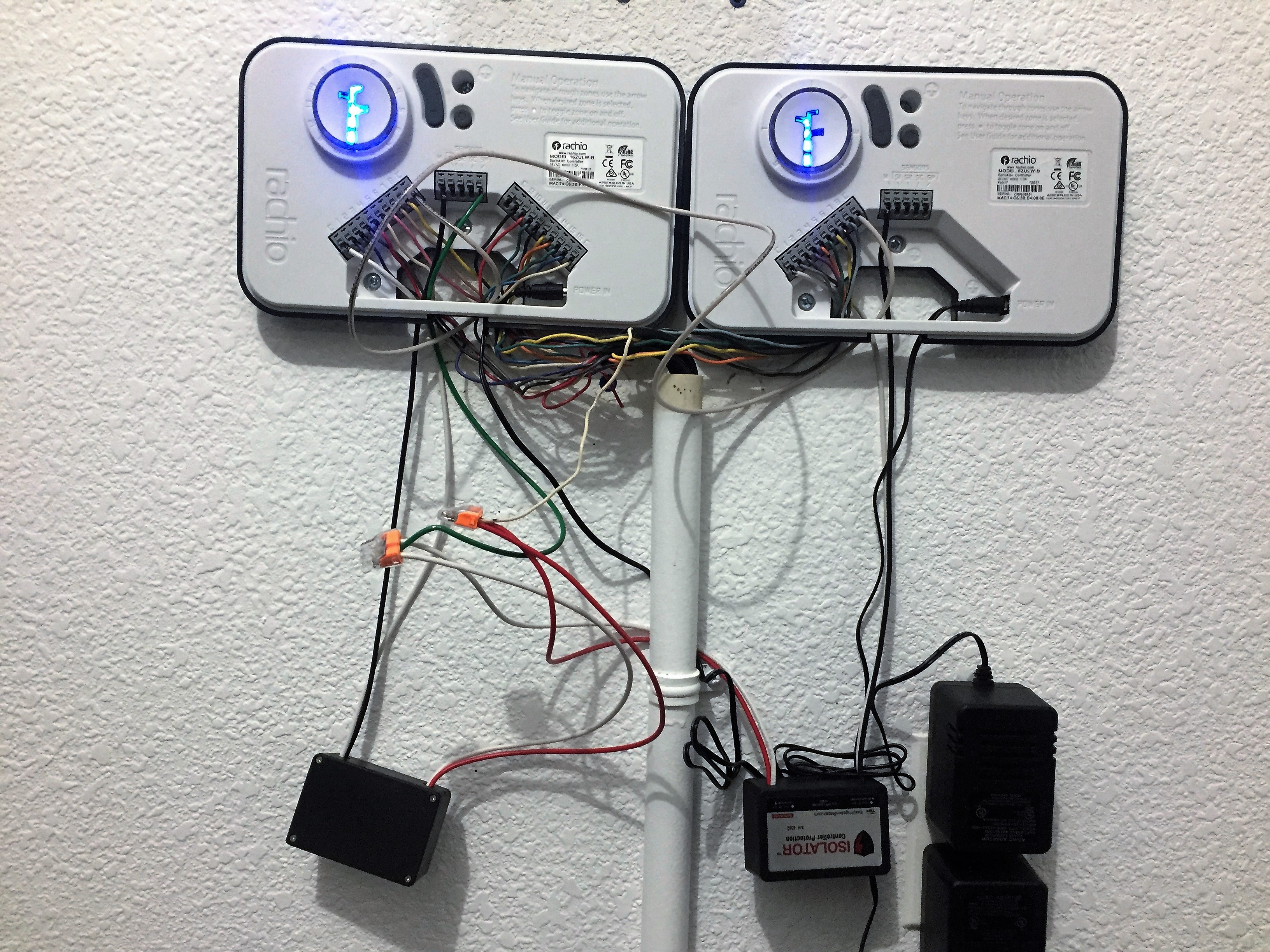
Had to go out to my Rachio to figure out what went wrong.
I discovered that SP terminal is pretty much connected to Common, and SC terminal actually carries voltage relative to Common.
Please connect your green wire to the SC terminal to get the setup working, not the SP terminal as I originally thought.
@elite1, were you able to get your system running yet? If not, I’d recommend we attempt to test on one controller to remove the Isolators from the mix and confirm your master valve and zone(s) are activating correctly.
Are you running both a master valve and a pump? If you have a pump, I assume you have a pump start relay?
@Gene, thanks for jumping in to help! We’ve had users attempt this wiring in the past, but due to how @elite1 has his power adaptors plugged in (upright and upside down) we do risk a polarity issue:
As such, I’d recommend removing the jumper wire and testing on one controller until we know the master valve (and pump?), and zone(s) are working properly – then we can sort out the isolator wiring; which for reference, originally looked correct @elite1
[details=Seems I was wrong (my original post)][quote=“emil, post:11, topic:7344”] @Gene, thanks for jumping in to help! We’ve had users attempt this wiring in the past, but due to how @elite1 has his power adaptors plugged in (upright and upside down) we do risk a polarity issue
[/quote]
I was pretty sure that power supplies were fully isolated from live and neutral so connecting one voltage bus (common) should not have presented a problem (and it doesn’t look like it did). If we were to connect a second bus (power) than polarity differences would cause an issue.
Isolators are not much more than a fancy relay, they do not generate power on their output, instead they short their outputs together. In order to work they need to replicate the function of the M terminal. M terminal should supply power to the master valve whenever it is turned on, now it shorts red and white wires of the isolators (otherwise connection is open). Original isolator wiring would short the master valve to common (not much usefulness there), whereas we need to connect it to power rail in order to replicate operation of the M terminal. I originally thought that SP is the power rail (it being associated with Power and all), but discovered that SC is actually a power rail. So to fix the wiring the green wire @elite1 is currently using should go to SC terminal.[/details]
I apologize in advance, I’m used to the switch type isolators, not the type used here. Whereas normally isolators would work like a relay, these work more like a power supply. After going on their website I see that these isolators do indeed output power to the output, not short their outputs together.
I’ll leave the troubleshooting to Rachio team (as I should have done), since I am not sure how the isolators you are using work exactly. Are both output wires isolated or just one? Is commons (white) a passthrough when isolator is energized or is isolation maintained throughout?
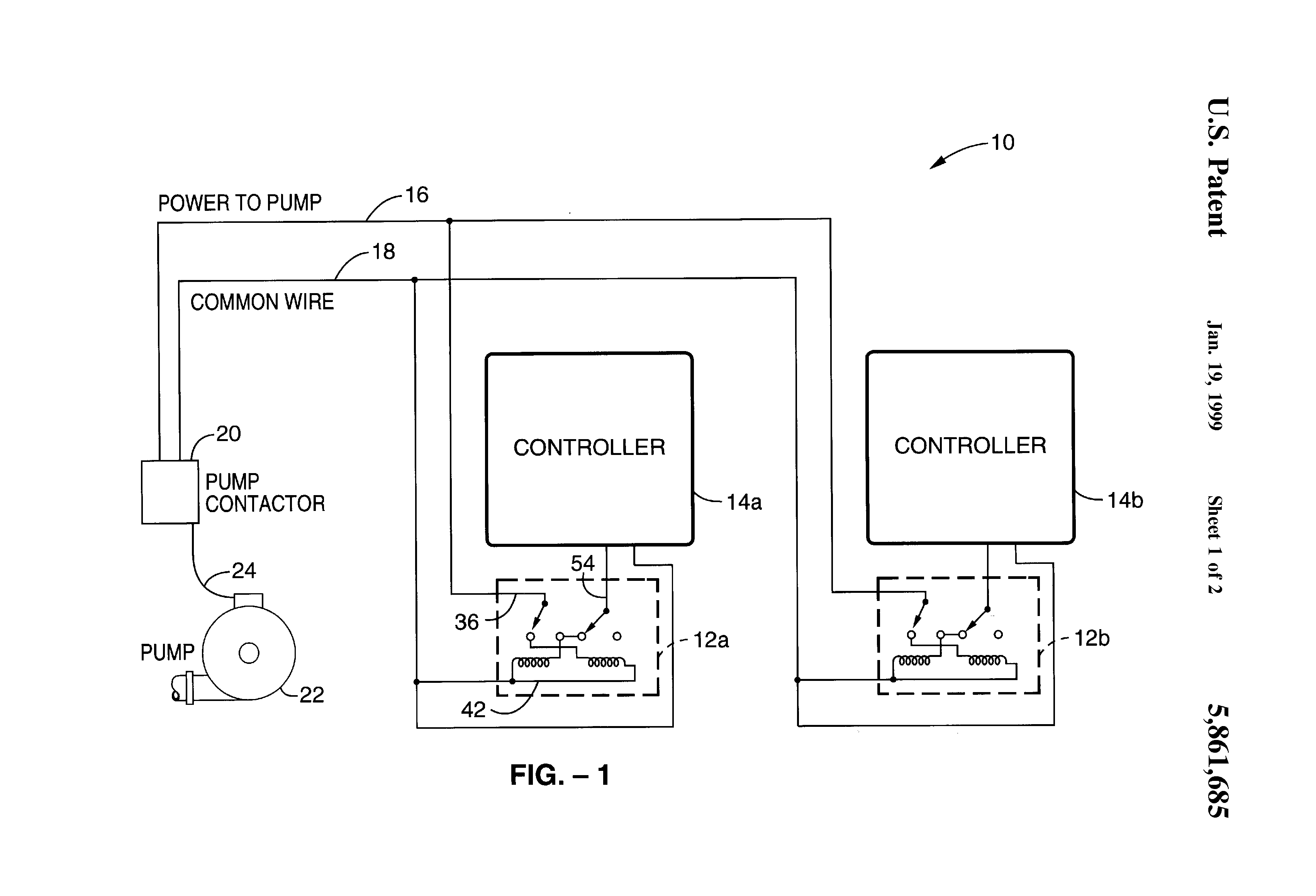
I had to check their patent to figure out how this isolator works. It is not really an isolator in a typical sense, more like first come, first serve relay with all of the commons tied together.
Not having one of these units on hand, there are two possibilities:
[details=Extend to see what would be true if White cable is Commons]
Looks like if you are connecting the white input wires to commons and connect two output white wires together, you are essentially already tying the commons together and no longer need a new dedicated cable doing the same thing, you can undo the step 3 if you need more available common terminals.
Looking at this schematic white isolator wires are already connected (internally) to the C terminals of your controllers. You can remove the green wire all together without affecting anything. I would check the master relay as recommended by @emil[/details]
Extend to see what would be true if Black and Red cable are Commons
I have a hunch that they have actually switched what is being controlled, from power as described by their patent, to commons as their instructions would hint at. This is the only thing that would make sense with their instructions for Diagram B (if commons are tied together, Diagram B would not work).
In this case Ohm test would show close to 0 Ohms between black input cable and red output cable, if this is so, than I would try flipping white and black cables around and connect master valve to white output cable, instead of red wire.
I can put a power strip on the plugs to eliminate the reverse polarity. Almost forget to mention. I dont believe that i have a pump and just a Master Valve.
First thing to try would be connecting you master valve directly to M port of the left rachio (make sure to disconnect the isolator currently connected there) and turning it on (the reason it has to be left one is that your valve commons are connected there at this time). You can disconnect the common link for this test.
Make sure it is working for one station, if not you need to locate your master valve and check the connections on the valve end.
Relays would need to be configured in a way I recommend. These should work well from the 24V signal from M terminal and can be connected in parallel to short Master Valve line to power rail SC.
You can use these outdoors or indoors for about half the cost of the recommended isolators.
Also if you have set your automatic watering times far enough apart to ensure that only one controller will be running at any one time. You can also try running both controllers with one power cable. Rachio should correct me if I am wrong, but controller draw is less than of a valve and 1 amp supply currently supports 3 valves + controller, which should be enough to run 2 valves + 2 controllers. I can’t test it, since I don’t have a second controller. But you should be able to run two common cables, one connecting one of C terminals between the two controllers and the other connecting SC terminals, essentially bridging the power to the other controller.
You can solder the wires on for a best connection, or crimp quick connects to the end of connecting wires.
Connect Terminals 7 and 8 of each relay to one of C and M terminals of independent controllers (polarity does not matter). C Terminals of the controllers can be shorted together.
Connect terminals 3 of one relay to terminal 3 of another, tie both to master valve line.
Connect terminals 4 of one relay to terminal 4 of another, tie both to SC terminal of one of the controllers.
This is it, you should have a true isolation for $20 or so.
+++ You will get an added benefit of seeing an LED on the relay when the master valve is ON.
Got the system to work, even during the rain here in Denver Went with the simple wire connection with one controller, found master valve and bypassed the solenoid, all working now.
 It is working?
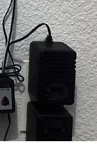
 Went with the simple wire connection with one controller, found master valve and bypassed the solenoid, all working now.