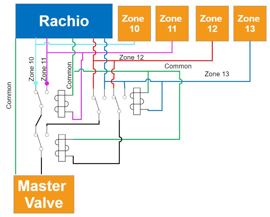
I need to split a zone into four zones and I’m using NC DPDT relays. I’m only using one side to make them SPDT I found a design on here that I am able to use to split it into two zones with relays. It works perfect, my issue is with the third and fourth zone. Here is the wiring I have created. I’m using four relays and not wiring anything to the NC on relay 3 and 4. I do have the common to my valves, I just didn’t draw it. Right now zone 10 and 11 work great. However if I activate zone 12 I am getting some current flow into zone 10 and I’m not sure why. Please let me know if I’ve made a mistake with my wiring, if my design is wrong, or if it can be improved.
Update*** Bad configuration deleted
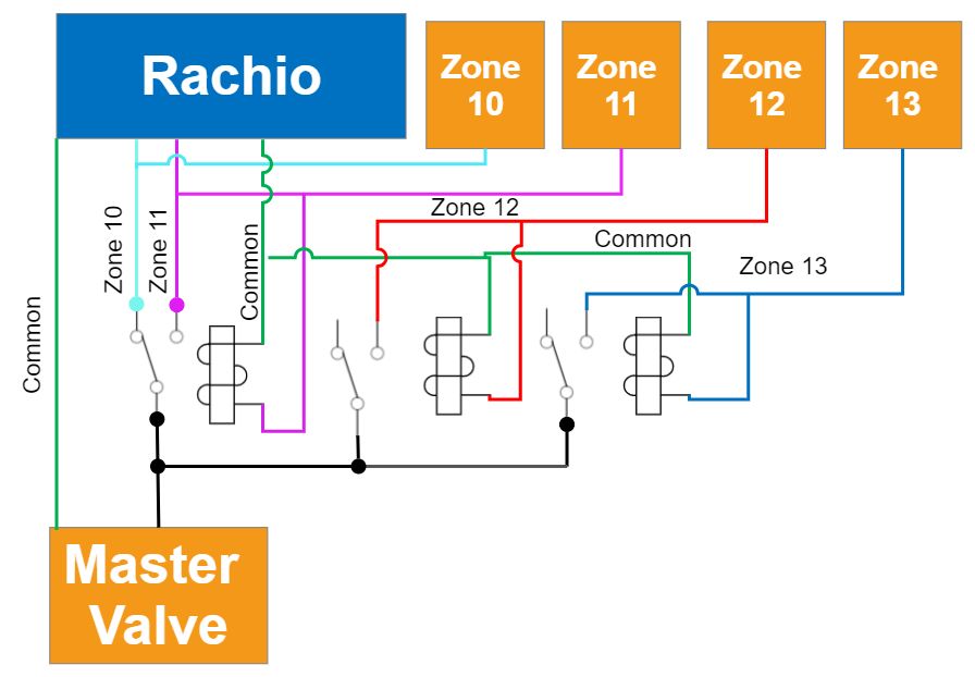
Alternatively, would this configuration work? Sorry I am awful at drawing these. I haven’t tried it yet. I think it would isolate the relays to being only run a master and slave valve at a time.
The problem with both designs is that Red and Blue lines do not have the source of power, even if the idea was to backfeed the power via the relay, related solenoids would not be energized, since they are driven by the said red / blue lines.
I think it would be helpful to work backwards, from from the relay design but from control design. How do you envision to run zone 12, for example, using zone 10 / 11 outputs?
If you need to run these zones on a schedule, than you could use a timer relay(s) in order to divert power to appropriate zone valve based on the time. For example running zone 10 at 7AM would water zone 10, but running it again at 8am would instead activate zone 12, etc… Programmable relay (like this) is one way to accomplish what you wish. To avoid having to buy a relay for every zone, you can switch commons instead of zone wires. This way you can have a whole groups of zones activated using a single relay.
Edit: I see you’ve edited your post to update the second schematic, but I fail to understand why you are driving the master valve via relays, instead of directly off of M terminal. Second option still requires four outputs on Rachio to drive four zones, so the purpose of the relays are lost on me.
I did the wiring for the second configuration and it worked. I’m not sure why you say it doesn’t have power. The power would be coming from the unit and all of the commons are wired in, I just didn’t draw them on the other valves.
I don’t want the master running non stop when I’m using all the other zones. The master is only a master for 10-13. Additionally, I have another separate zone that I have split as well. I tried the M terminal route and it ended up messing up the other split zone. I guess there isn’t enough power to operate three valves at the same time.
Reason why I said red and blue wires were not getting power, is that prior to your updating your second drawing it, like the first, didn’t have red & blue actually connected to rachio. They would need to get power from black wire, but the relays to do so are driven by red & blue signals…
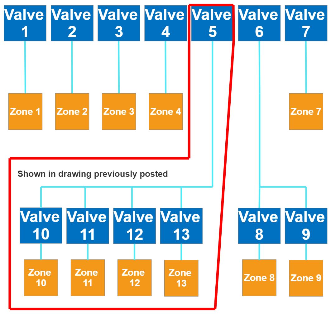
ah, now I see how everything is setup. The title of the thread made me think you are trying to run more than one zone with a single Rachio output, whereas you are trying to activate a valve based on state of any of four zones. I think you have three options:
Simply convert valve 5 and 6 to always be ON, this will mean a longer pressurized line but requires minimum effort.
Add a system wide master valve in addition to step #1, this way the extended pressurized zone will not be an issue since at least one zone will be active to relieve said pressure.
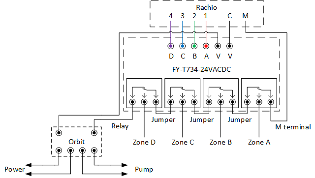
Use relays as you thought to do, I recommend this module (amazon link) of four relays in one since it will take up less space. I’ve previously have recommended it to selectively deactivate the master valve, but the system can be run in reverse to selectively activate it. If you’ve already bought the relays, you can use them, just treat every relay which is part of a module within the diagram as a separate entity.
When I’ll get a chance, I’ll update the schematic to show how to wire it up, but in general you’ll want to connect power from Rachio’s M terminal to every NO terminal (Labeled “Zone A” through D here) and the “Master” valve connected to the rightmost common (labeled “M terminal” here). This way an active zone will connect power to appropriate common of the relay and others on the right will pass it on to the rightmost terminal.
I know you’ve already mentioned that you’ve had issues with running valves from master valve terminal, but what exactly happens when you try to run both valve 5 & 6 from the M terminal leaving other zones controlled individually?
Wiring wise everything is working perfectly fine with the configuration I drew up. My issue now is water hammer on the very last valve. I have an idea of modifying the manifold that I think will work to eliminate it.