I am trying to wire the Rachio 3 in place of the RainBird ESP-8 and it looks like I cannot connect my Master Valve wire now that I removed the Rainbird transformer. The transformer has 2 orange wires that connected to the Rainbird panel, a white wire & green wire that connected to the COM on the rainbird panel and then a black wire that connected to the MV on the panel. I used the black, white and green wire to connect up the Rachio plug into the housing and now need to know how to wire a black, white, and green to the Rachio panel.
@vjohns08 - is the Rachio external enclosure being used?
If so, the hot wires from the Rainbird transformer connect to the external enclosure and then the Rachio transformer plugs into a socket in the external enclosure.
If the Rachio external enclosure is NOT being used, then one needs to connect the hot wires to a plug in an outlet box and then plug the Rachio transformer into it.
That will leave at least two Rachio C(ommon) terminals open - one for the white and another for the green wire that were previously on the RainBird COM terminal. Then the brown (black?) wire that is in the RainBird MV terminal goes to the Rachio M terminal. The zone wires go one to one from the RainBird to the Rachio.
Do not connect the orange wires from the RainBird to the Rachio! And do not connect 120 VAC wires directly to the Rachio - use the Rachio provided transformer and plug.
Hi, I am using the Rachio external enclosure, there were 3 wires coming from the Rainbird transformer that was wired into the Rainbird connector panel. Black wire from the transformer to the MV on the RB connector panel, White wire from the transformer to the COM on the Rainbird connector panel, and green wire fro the transformer to the COM on the rainbird connector. I took the black wire and connected it to the Rachio external enclosure connect for the rachio plug and attached it and then did the white tot white and green to green to the rachio outlet. The issue now is that i do not have those wires available to go to the rachio connection panel for M(main valve), white to COM on the rachio connection panel or green. That is were I am stuck, do I run jumpers from the outlet wires to the rachio M, COM, and green?
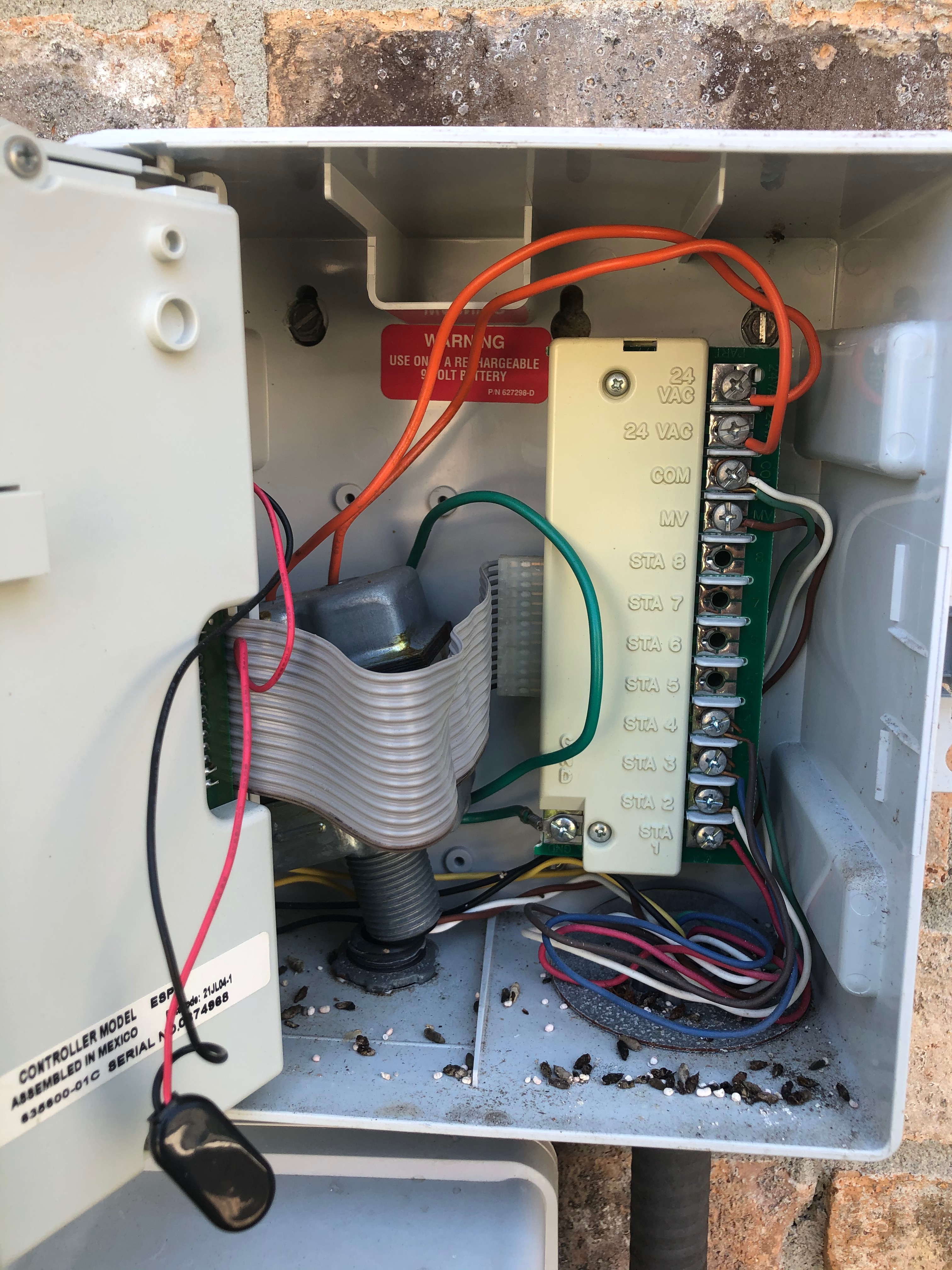
The problem that is see is that the rainbirds black(hot), White(com), and Green wire connected to the rainbird connector panel. Then as the picture shows a ribbon cable from the connector panel plugs into the rainbird panel. On the rachio if you use those 3 wires to wire up the rachio plug then you have to figure out what to do about the additional wires need to go to the rachio M and COM connectors. I hope that helps.
@vjohns08 - the wires coming into the RainBird transformer should be carrying 120 VAC and will fry the Rachio if connected. The green wire on the RainBird transformer should go to the GND terminal (the picture is a little obscured).
I see a brown wire for the MV. I really don’t think the white wire from the RainBird transformer should be connected to the Rachio - one is cross connecting a high voltage and low voltage system - even though the white wire should be the neutral and not carrying any current.
Can you post any more recent pictures with the Rachio enclosure or after the black collar was removed from the RainBird.
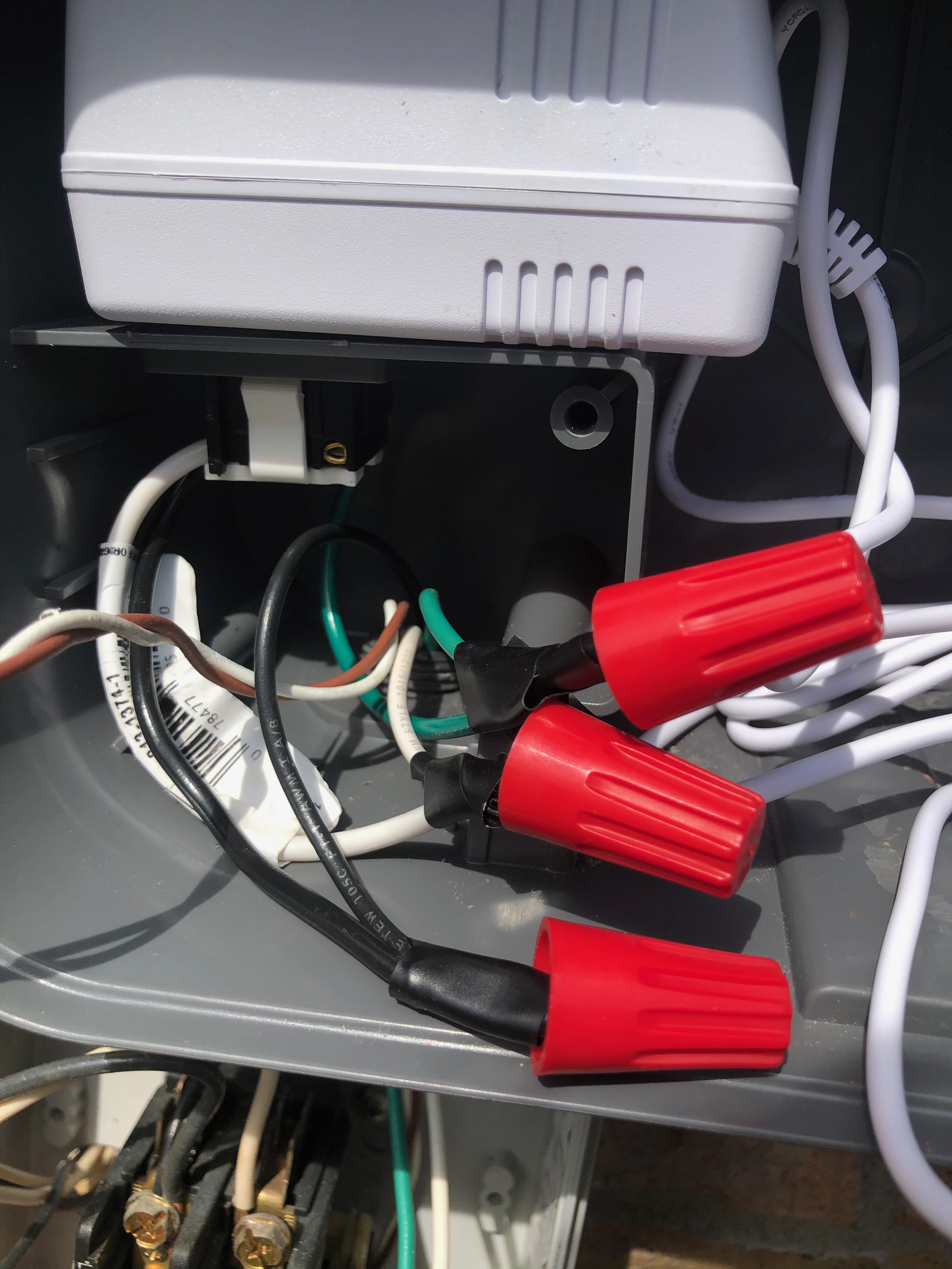
This is the latest on the rachio outlet, I took the black from the rainbird transformer, white from the rainbird transformer, and green from the rainbird transformer and wired it in for the rachio outlet. I totally removed the rainbird transformer. The Brown and other White is not connected at this time I just pulled it thru with the other wires
@vjohns08 - I think I see what is going on. The small thin white and brown wires, that are currently not connected, came up through the RainBird high voltage port, but are probably low voltage wires going to the master valve or a pump start relay.
Ideally, I’d move those wires to the other wiring bundle/port. If that can’t be done then make a small hole to get the wires out of the high voltage area. Connect the white wire to a Rachio C terminal and the brown wire to the Rachio M terminal. Then hook up the other low voltage wires as they were on the RainBird, there will be a second C terminal to put the green wire in.
Was a test run made before the RainBird was disconnected to make sure all the wiring and solenoids worked?
Hello, I did test all the zones prior to installation and all was working fine. The small thin white and brown wires were not connected to anything in the RainBird controller, I will verify that the wires are low voltage this morning. I don’t won’t to plug these 2 wires in and blow the board if they are running high voltage. My irrigation system has a 1.5 HP irrigation pump on it.
@vjohns08 - with a pump there should be a pump start relay. That is what I think the white and brown wires are going to. Can you trace the wires from the pump start relay back to the enclosure? If those wires do go to the pump start relay they won’t have any voltage on them now.
You are correct, the white and brown lines from the pump start relay does not have voltage. Black is hot. Do I connect the brown wire from the pump start relay to the M and the white to the COM on the Rachio connection board?
@vjohns08 - Correct. Brown to M and white to either C on the Rachio. Don’t forget to enable the pump start relay/master valve option in the Rachio app.
You’re on your way. Enjoy and welcome to the community.