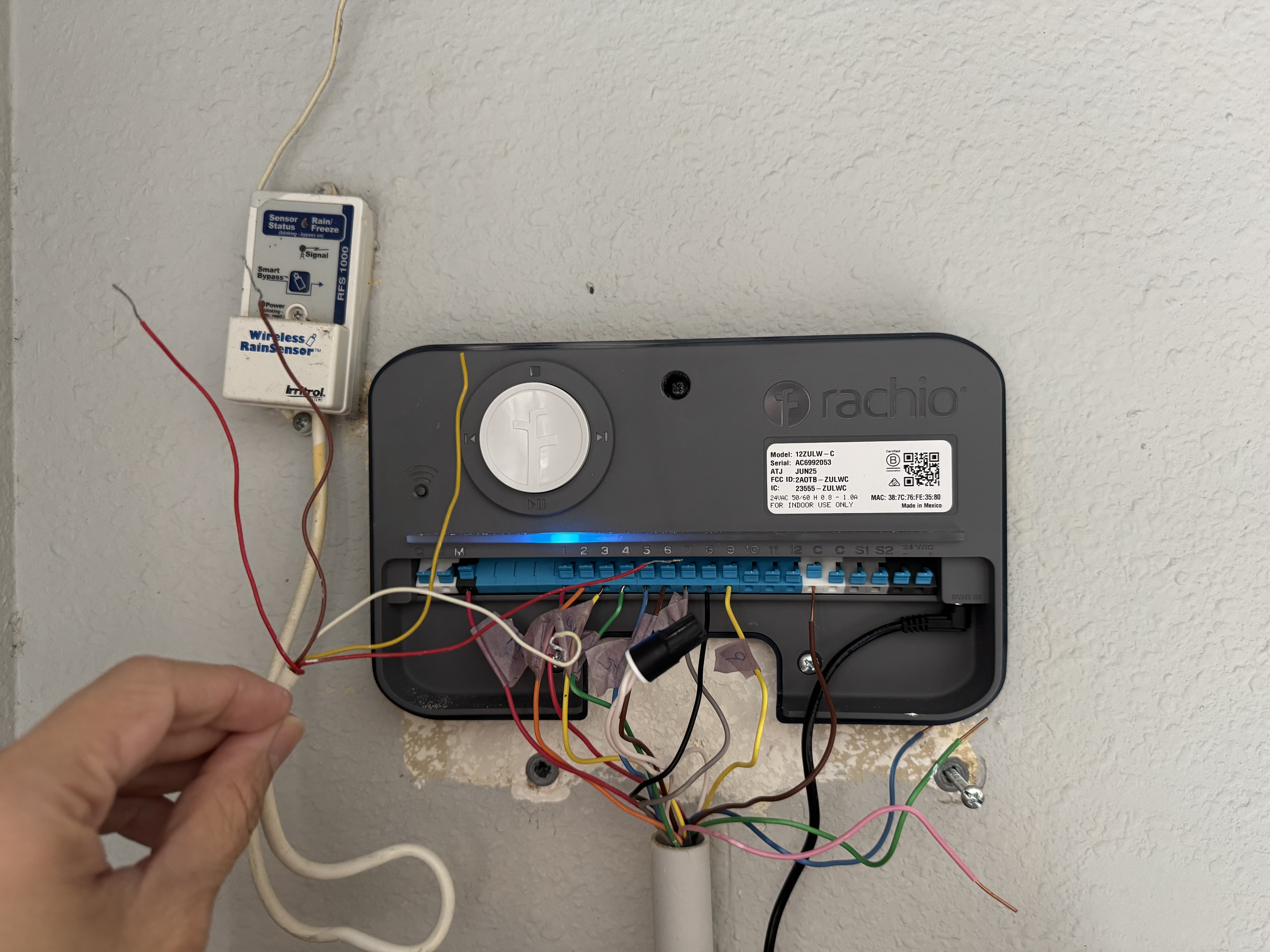
I’m having trouble figuring out how to connect the AC power supply into my Rachio 3 outdoor unit. It is AC powered (with long wire running through the house to outside) and was plugged in according to the picture below. But I’m having trouble figuring out how to align the blue red and white to the Rachio black white and green. Can anyone help?
I recommend using the power supply that was supplied with the Rachio. As you will notice with the supply that it connects to the Rachio with a barrel connector (you cannot wire directly to your Rachio). If you cannot use that supply, then continue on.
I would suggest first checking the transformer output (volts AC or DC and how many amps or watts). If it is all good (I would guess it is, but I suggest posting the information to double check), you would have to put the same size barrel connector on the end of the existing wire. I personally do not like to cut it off it the supplied supply, but that is up to you. The white would not be hooked up anywhere, so you would only use the red & blue. Since it is AC, I do not believe you need to be concerned about which way you hook the connector on.
Hmm not sure I 100% follow. I have the outdoor Rachio cover which has hardwiring on the inside that I assumed I could connect the existing power supply to. Then I could plug in the “supplied” power supply into the outlet inside the case and the barrel into the Rachio itself. But the issue is that with my old rainbird the power cords are red blue and white (which oddly was the ground wire), and the hardwire cables by Rachio are black, white, and green. I assume the old white will connect to green as they are both ground, but unsure about the black and white to the red and blue
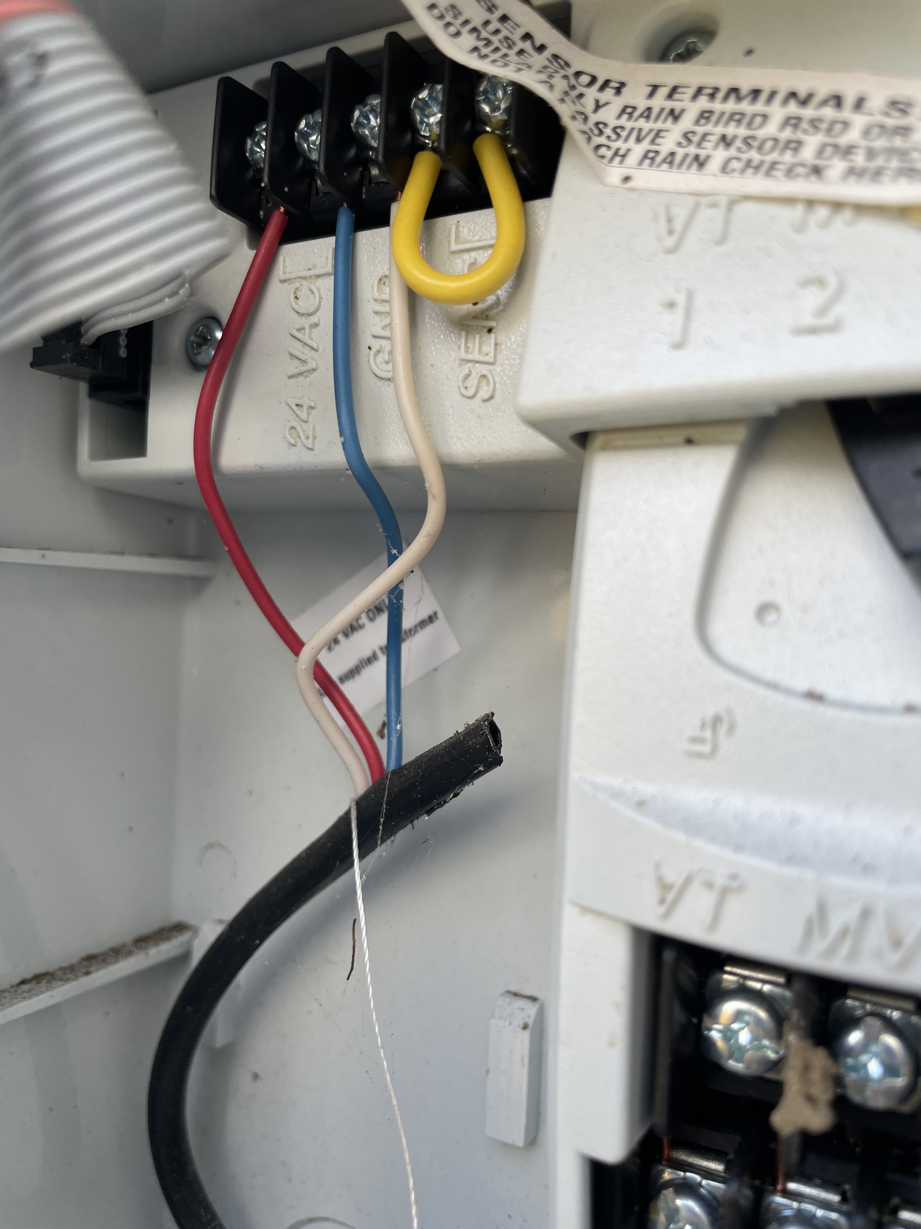
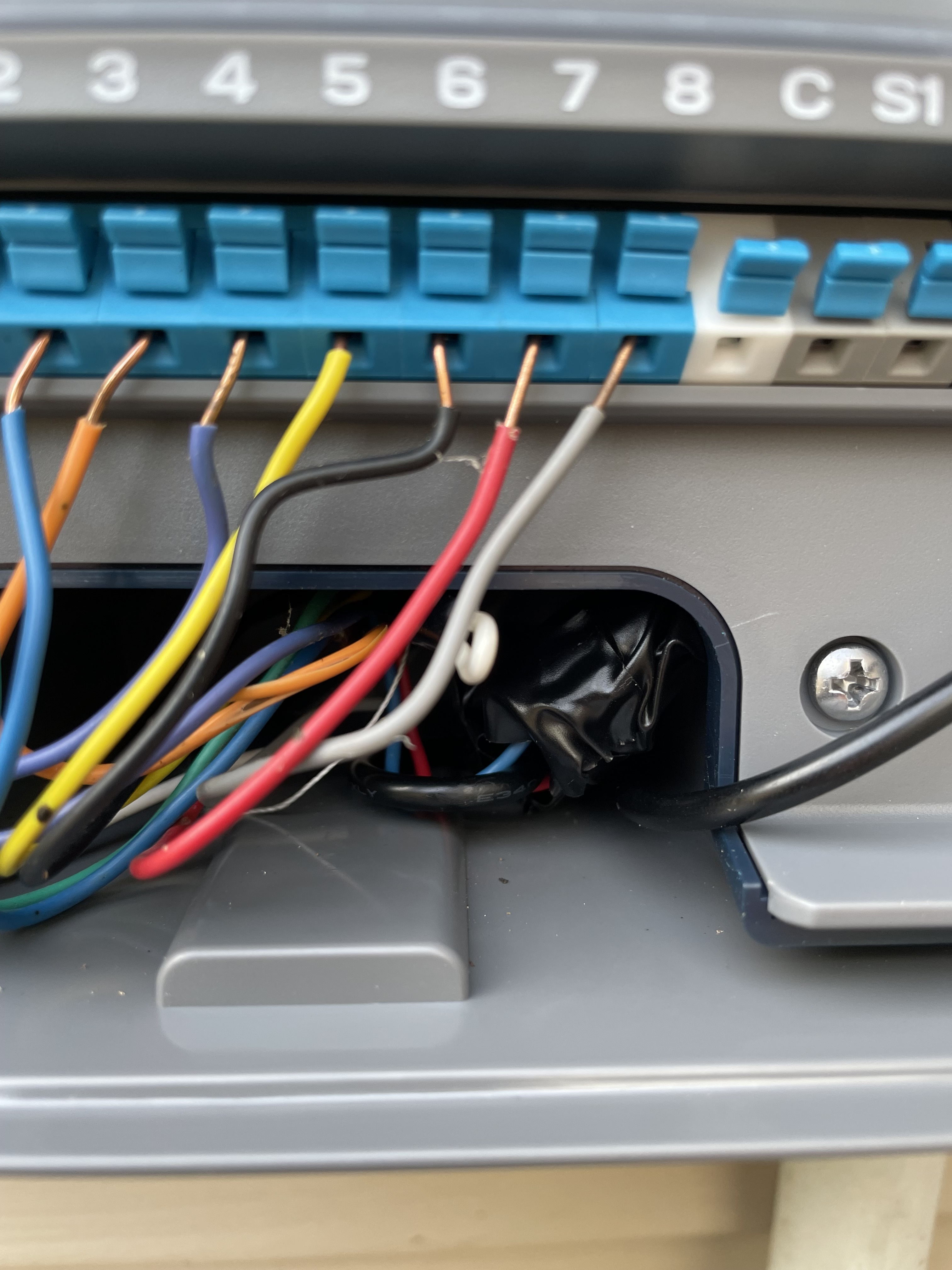
Here is a pic of how the rest of the ESP-ME was wired
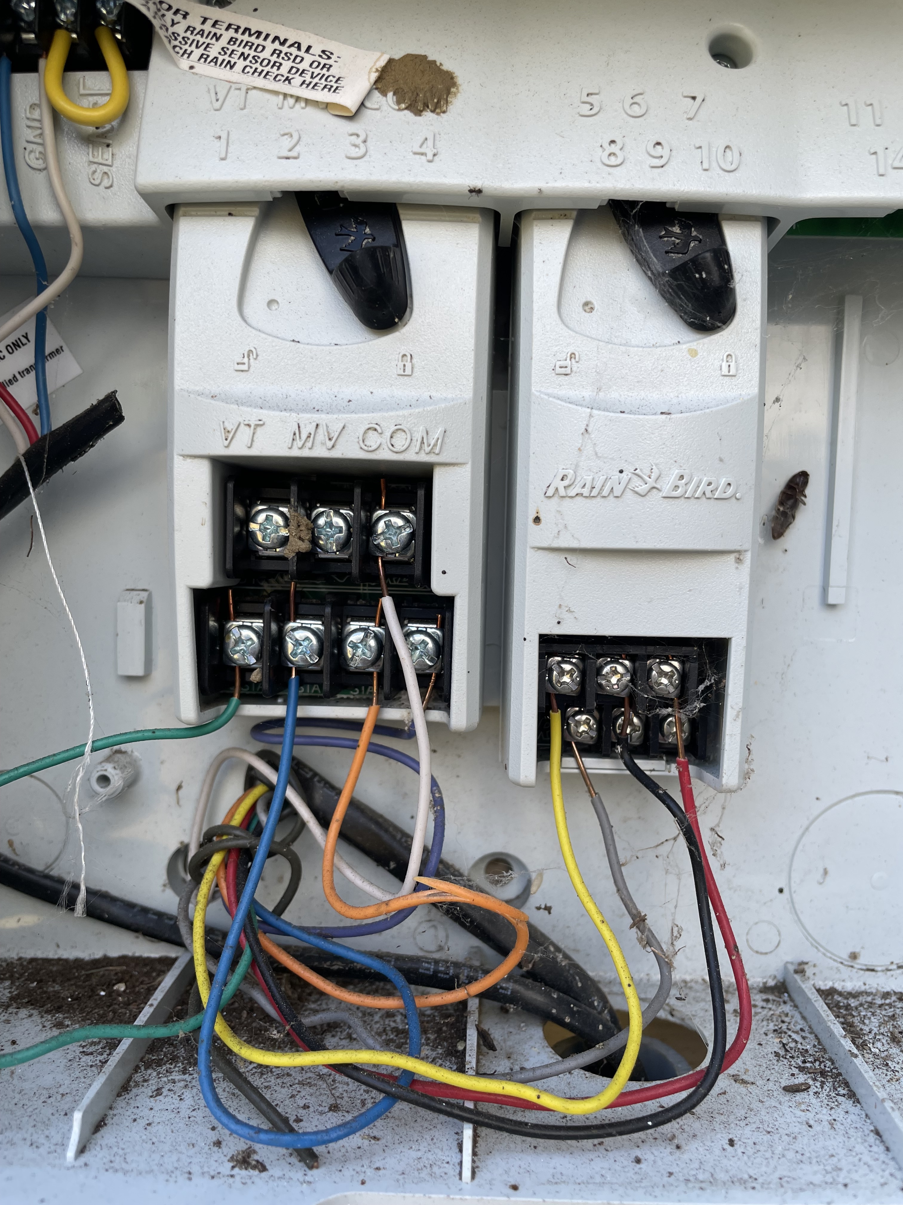
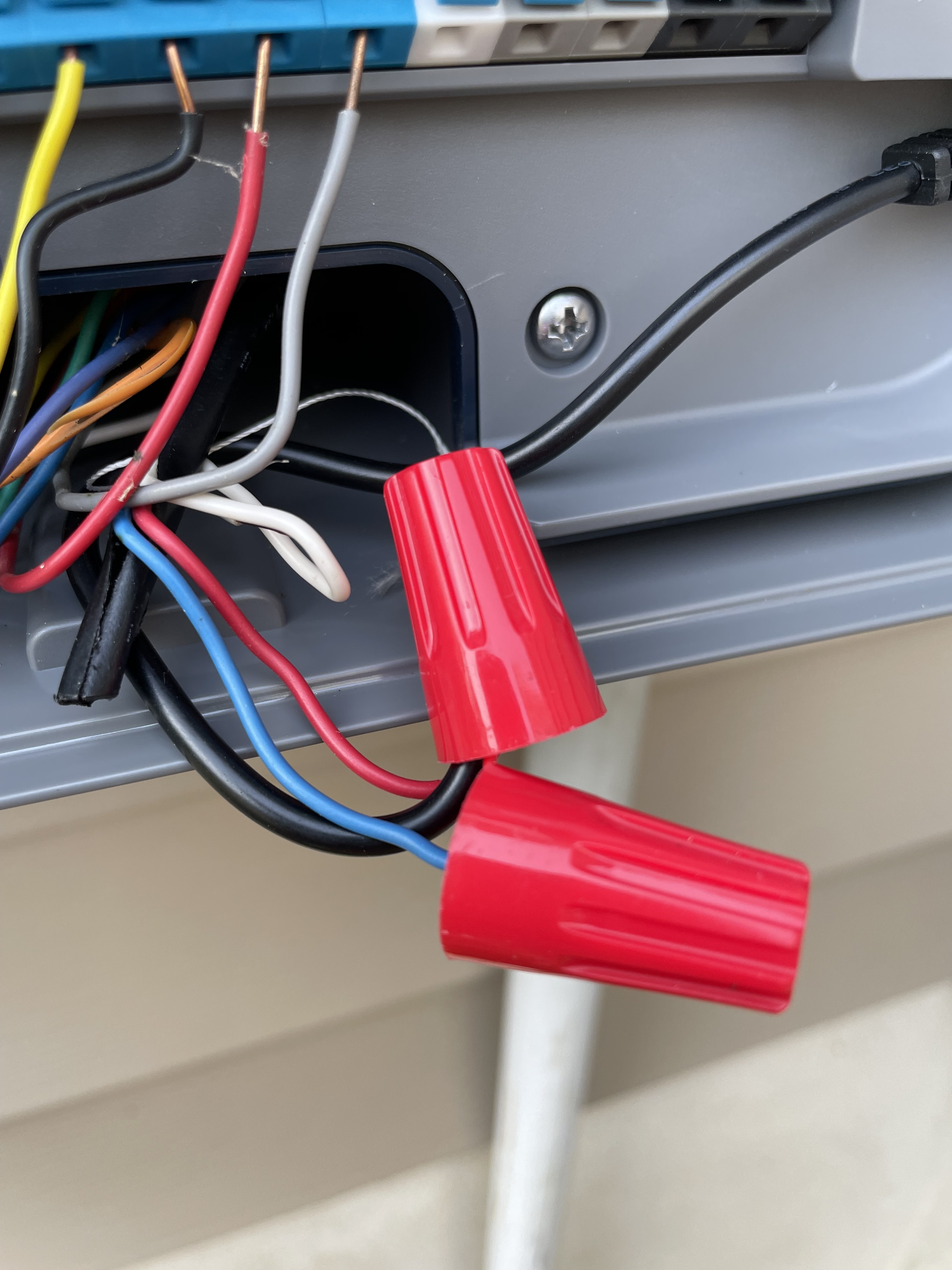
To make things extra co fusing, there is a white common wire plugged in this second picture (but not the same area as the red/blue wires). And I’m unsure if that white wire plugs into the white wire in the hardwired outdoor case, or directly to a common wire port on the Rachio itself
I’m beginning to suspect that the red wire from my original rain bird power supply is actually the “hot wire” 120 VAC that would need to connect with the Rachio outdoor case black wire, the rain bird blue wire is rhe low voltage common wire, and the white is the ground. And then the white wire that was plugged into the “C” in my original rain bird that was in the 2nd pic would plug into a C port of the Rachio. But lmk what you think @Thomas_Lerman
I think I see where the confusion might be coming. I looked up the ESP-Me, man_ESP-Me-WiFi-Compatible_en.pdf, and the power that gets wired into the controller is 24V AC (not sure how many amps or watts). This tells me that the other end of that wire is connected to some kind of transformer.
The Rachio power supply expects 120V AC and ends up with 24V AC going to the barrel connector. You cannot wire your old wire into the outlet for the Rachio. In the one case, you can get the right size barrel connector on the end (if it has the minimum amps/watts). Another case would be probably getting an electrician to run 120V AC mains to the outlet within the enclosure to plug the Rachio power supply into and its barrel connector into the actual Rachio.
The white in your second picture is wired to COM on the Rainbird. The other end of this wire goes to your valves. You would take the COM from the Rainbird and connect it to the C terminal on the Rachio as you said.
Ah, okay - so the long story short is I cannot really hardwire my old power supply into the Rachio unit. I don’t have an outlet near where the controller is mounted, it sounds like I would need to go the route of having an electrician run the 120V AC mains to the Rachio outlet or install a closer outlet on my home’s exterior with a cover that can protect the Rachio power supply. Is that right?
@Rguido3 - what I have done is to cut the wire on the Rachio supplied transformer, say six inches from the transformer, splice in the existing long wire run, then splice the Rachio barrel connector on the other end of the cable. One would then just plug that wire into the Rachio. As @Thomas_Lerman mentioned and you have discovered, the Rachio outdoor enclosure is designed from 120 VAC and then to plug the Rachio transformer into the plug in the enclosure. I would just run the 24 VAC wire to the enclosure and route it to the controller with another hole if necessary by the power plug.
Welcome to the community.
I literally just noticed that the Rachio actually has the 24V AC wire inputs directly on the unit….so I can just plug direct into that? That is so much easier!! And I wouldn’t have to use the power supply that way, correct?
No! Don’t back feed the Rachio unit. Those are designed for output.
Ugh, okay I will go with the splicing method you suggested. Will let the group here know if I still have issues!
It sounds like you got it. Yes, please keep us informed
@Rguido3 I know that wasn’t the answer you were looking for, but if you search through the forum you will find where others have blown up the electronics on those ports by connecting the output from a transformer to those ports.
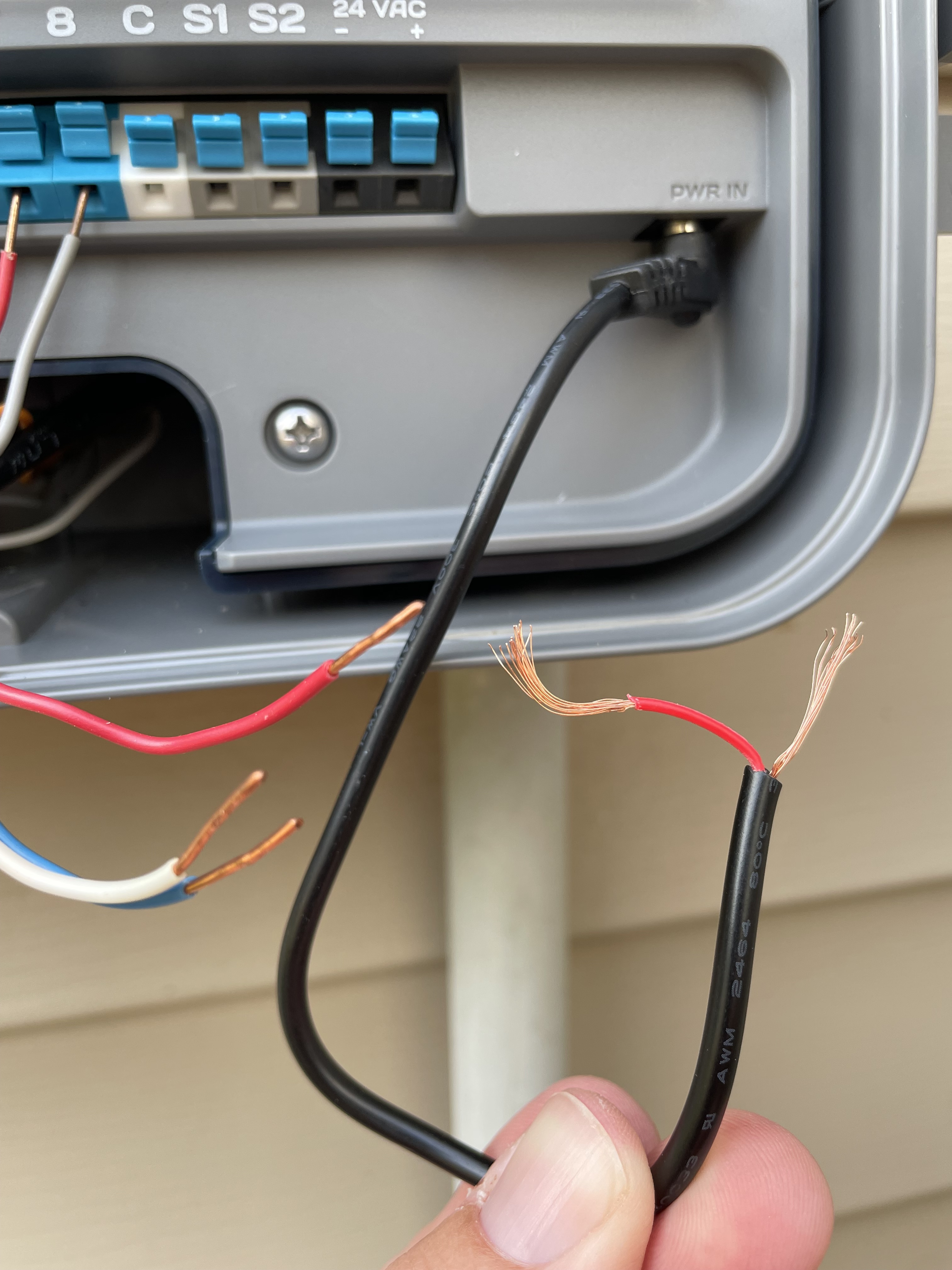
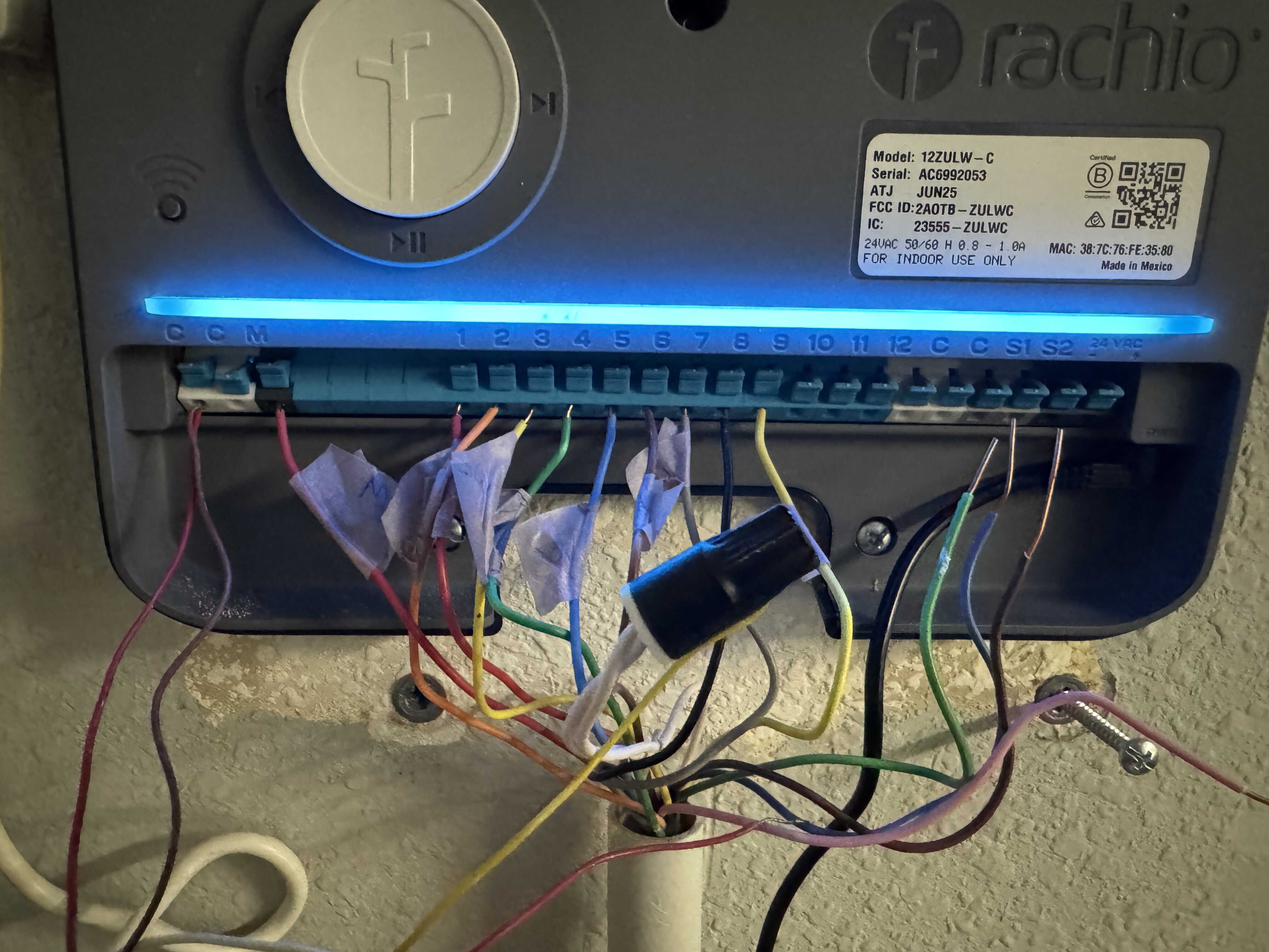
OK, the splice method worked - I spliced part of the rachio power cord before the barrel end (pictured below), and then did the same inside where the transformer plugs in. Plugged it in and double checked both areas where I spliced and there doesn’t seem to be an issue. Device turned on, I set it up, and tested all sprinklers without issue. Thank you all for the help!
1 Like
Do yourself a favor and cut some of that exposed copper lead wire off. You’re asking for trouble with that much bare copper exposed out of the terminals.
Thanks @vsocks, do you mean on the zone wires? So just snip them down a bit and plug back in? I think I covered all exposed copper on the AC lines w the terminal caps and electrical tape
Yes that would be correct!
I also have the Bird-rain system.
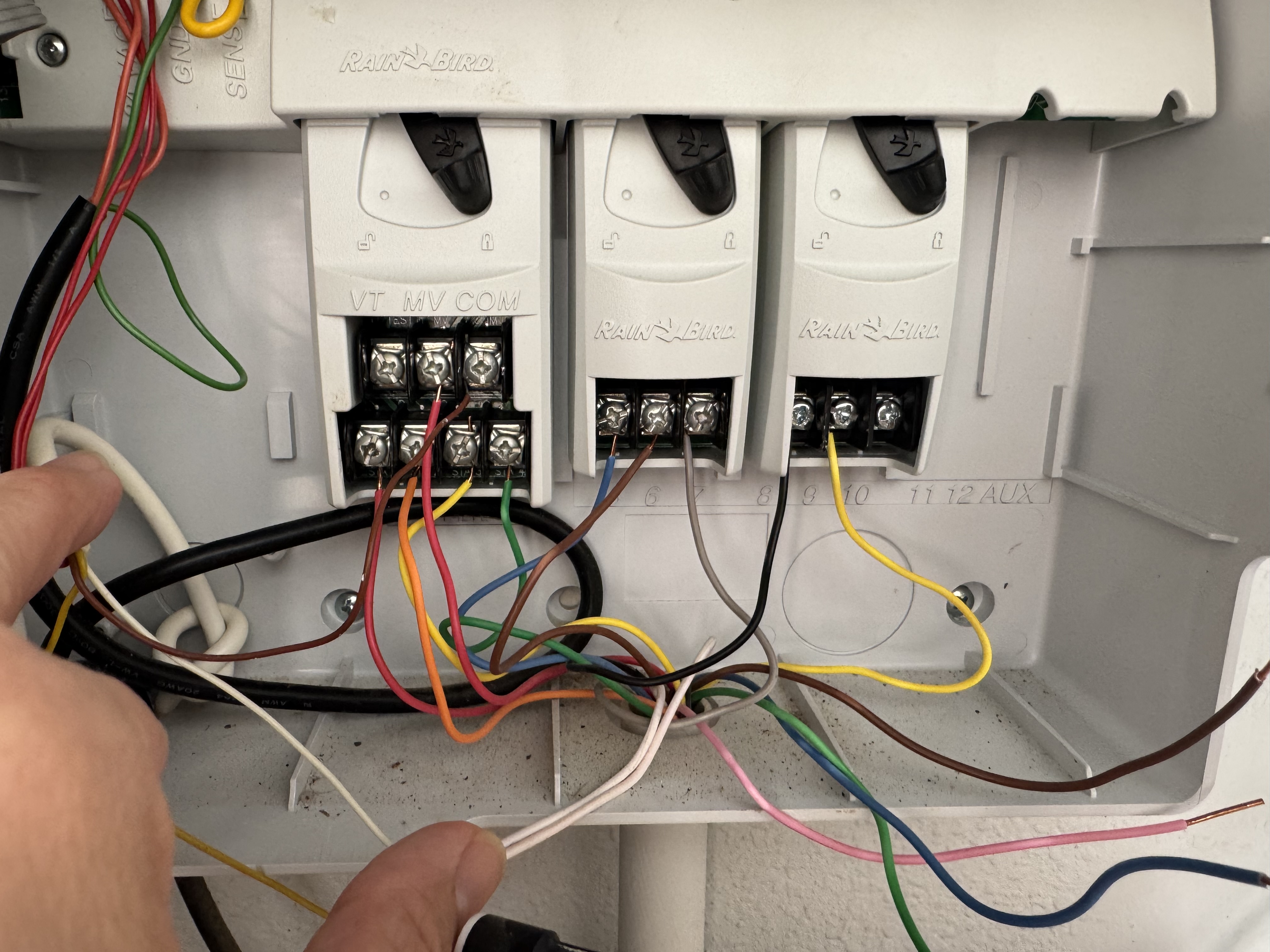
And wired as the instructions but when I run the test nothing happened… help! any one have a clue what I did wrong?
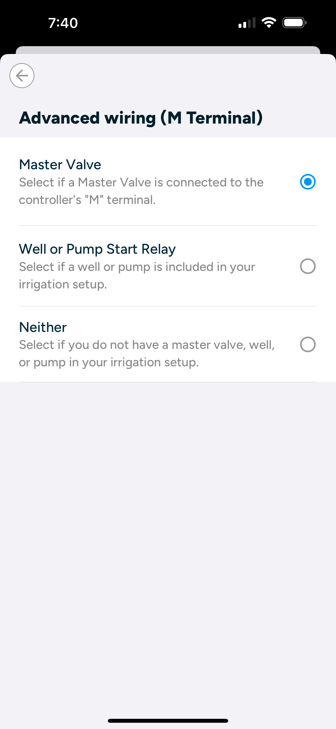
It is barely cut off in the first picture, but looks to me like no sensor is hooked up. Did you run it right before disconnecting the wires and if so, did all the zones work? I would suggest moving one of the common wires to a different ‘C’ terminal . . . they are all connected together. Did you configure in the app what the ‘M’ terminal is (master valve or pump)? Do you know where your master valve/pump is and how to manually turn it on after turning on a zone?