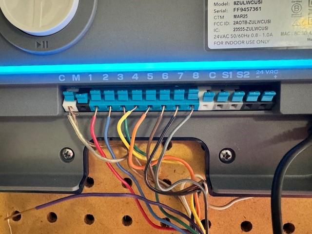
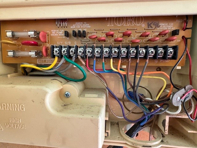
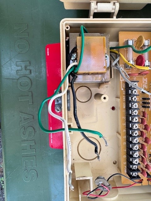
Hey all. Just got the Rachio 3 yesterday and am having trouble going from my old Toro system to this new one. I hope you can see the pictures I’ve attached showing the old wiring compared to the new. I know I have the right zones in the right slots, but I’m not sure what the original wiring on the far left is all about. I believe the first three slots on the left (G/Y, G/B and G) are for the hardwire system on the old Toro, but I guess I can’t be certain. I read a post where they said to only be worried about the common wires and the wires for the zones, and forget about everything else. That’s what I’ve done, but my zones aren’t working. I’ve tested all the zones and none of them work, even though the app says they’re running. I’ve tried running them from both the app on my phone and using the unit itself.
Not real handy with a multimeter, but testing each zone against the common gives me a reading of 12v. When I have the zone running, it gives a reading of 30v.
What am I doing wrong? Any help would be greatly appreciated!!
@Tafkap777 - It looks like the Rachio is wired correctly. The G/Y, G/B and G wires on the Toro appear to be the power supply, so those will not be connected to the Rachio.
Was the Toro system run right before converting to the Rachio to make sure everything was working? Is there a manual valve that could be closed that is preventing water from getting to the valves?
Thanks for the reply! Yep, my Toro unit was working just fine prior to making the switch to Rachio. I didn’t touch any of the valves, so they are all still open.
@Tafkap777 has it rained there recently? I don’t see a spot for a rain sensor in the old Toro system, so there could be a rain sensor installed in-line on the common wire? Do you have a rain sensor?
Another test is to take the common wire(s) out and a zone wire out of the Rachio and use the resistivity setting on the multi-meter to see if there is continuity in the circuit.
Once everything is working, it might be a good idea to trim down the zone wires so there won’t be as much bare wire showing to connect to something else.
Interesting. I do have a rain sensor, but it broke a couple decades ago. When I had new siding and roof put on, I had them remove the sensor. Maybe one of the commons is for that absent sensor. I’ll remove one of the commons (one at a time) and see if that makes a difference.
Not sure what the resistivity setting looks like on the multimeter. I have ohms, V with two different symbols above them - one set with a wavy line and the other set with one straight line and three dotted lines below that. Is it one of those? Is my ignorance showing?
Thanks for the tip on trimming the lines down. I’ll get that done once I get it up and running.
Found the continuity setting on my meter. Touching the common to my zones goes from a 1 to about a 1.8. Interestingly enough, I tested my commons with each other and got an audible sound when I did that. Makes me wonder if I’m supposed to be getting a sound when I test the common with the zone.
@Tafkap777 - ohms are units of resistance, so that is the setting you want. In the Toro picture there is a blue wire nut in the bottom right hand corner. I’m betting that is where the rain sensor was wired in. Could you provide a close up picture of it and maybe describe the wires, etc.
Some multi-meters will beep if there is a solid circuit - i.e. 0 ohms. An open circuit is infinite ohms. I forget what the value one will see when measuring ohms down the zone wire, through the solenoid coil and back the common wire, but there will be some resistance - which is good.
On the multimeter - the V with the ~ if for measuring AC voltage. The V with the straight lines is for measuring DC voltage. We all had to learn this at some point.
Thanks for sticking with me on this. Just for clarity, the rain sensor has been physically removed from my roof for several months now. The bypass switch is still on the wall, but not attached to anything (power or the Rachio 3).
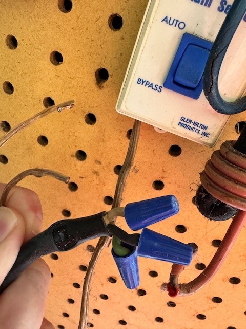
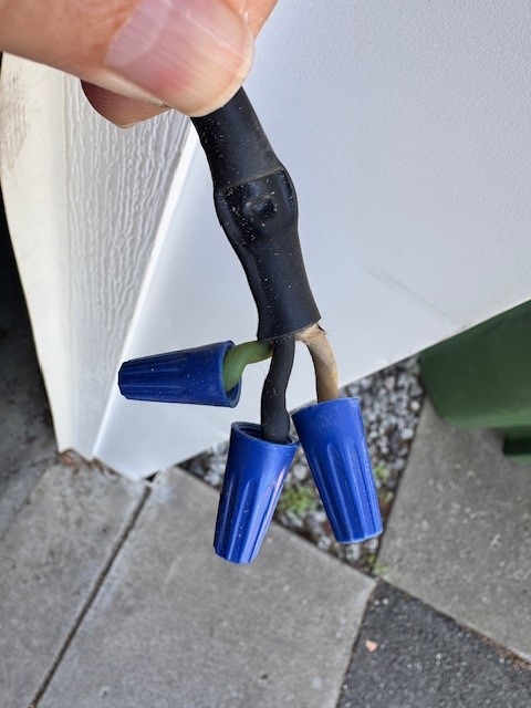
Here’s a picture of what was in the bottom right corner. The two wires on the left side are coming from my bypass switch, and the others are what powered my old Toro unit (it was hardwired). I will be properly capping off those wires and getting them out of the way all together.
I only saw one blue wire nut and a longer white wire. The photo that you provided has much shorter wire lengths in it.
Going out on a limb here … Of the two wires that are in the Rachio C terminal in the first picture, one of them looks to be stranded wire, versus solid wire that are in the zone terminals. I would remove that wire - if it already hasn’t been removed. I’m guessing that it goes to the Bypass switch. Next see if you can find the white wire in the photo above and place it in a Rachio C terminal. Many times installers will use a white wire for the common wire. I would expect the white wire to be a solid conductor, just like the zone wires. Then try to run a zone and report back.
Sadly all of the wires besides the wires for the zones are stranded.
Here’s a closeup look at the white wire in question. It came from what I’m assuming are the hot wires to power the old system, and lead into what I’m assuming is a transformer of some sort.
The white wire that still has the cap on it is also stranded. I’ll gladly try that one in a common terminal, but just want to verify with you that I can do this. I don’t want to put a wire in there that’s carrying 120 and fry out the Rachio.
There were just two stranded wires coming out of the bypass switch. They have a clear jacket on them that look suspiciously like the two wires I’m using as the common. Is it possible they aren’t the common wires? Which ones could possibly be the common?
I figured it out! As you can see in my very first pic of my new wiring on my first post, there is a purple wire on a white wire that aren’t connected. The purple must be for an unused zone, but I thought the white was for the battery backup on the old unit. Put both of them out of my mind until you were talking about how none of them should be stranded.
I put the white one in and my zone popped on when I tested it. While I was there I trimmed down all the wires so the copper isn’t showing any more.
You are the greatest! There’s no way I would have figured this out on my own. All your questions and guidance made me figure it out. I truly appreciate your patience and willingness to help me work through this!
Time to set everything up and get my lawn watered.
It apparently… looks GOOD . to read your post here ; Toro hasn’t come up with any New Update from their Controller like Lawn Gene ( I believe ) ,… but Your new product ( Rachio 3 ) will be easier and better Now ! Welcome to Rachio Community!!