I have below wiring on my current hunter controller… The C wire and station wires are understandable but I can not figure out how to connect the rest of the wires. I could not find any wiring similar to mine in the forum for guidance. Can anyone help me out please?
It looks like you have a rain sensor and no master valve. It is hard to tell on some of this, but it seems like the following based upon your picture and LIT-185RevE (hunterindustries.com):
- The black wires going to 24 VAC are the power supply wires (input) and should not be hooked up to the Rachio. Instead, you should use the Rachio supplied power supply.
- The red, white, & blue wires to power and ‘R’ are for a remote controller, which would not be used with the Rachio as its remote is an app on your phone.
- You already know the zones’ red wires.
- The tricky one might end of being the white wires to ‘RS’ and ‘C’. The ‘C’ and one of the ‘RS’ wires are for a rain/weather sensor. The other ‘RS’ wire is a common for the valves. If you can tell which one, that should be hooked to ‘C’ on Rachio. If you cannot, you should be able to tell with trial & error or else with a multimeter if you have one. We can help you as needed there. I personally would not suggest hooking up the rain/weather sensor at this time. It gets hooked up differently on the Rachio and with the localize weather, you might not need that. Please let us know your thoughts.
1 Like
Thank you so much for the prompt and detailed response. Since I don’t have the multimeter, I will try the trial and error for finding the C wire in the RS Terminal. I will return with the feedback soon. Thank you again 
I found this information on the web about someone who is trying to work with a Hunter Controller that seems like yours.
I hope this is of any use
Phil
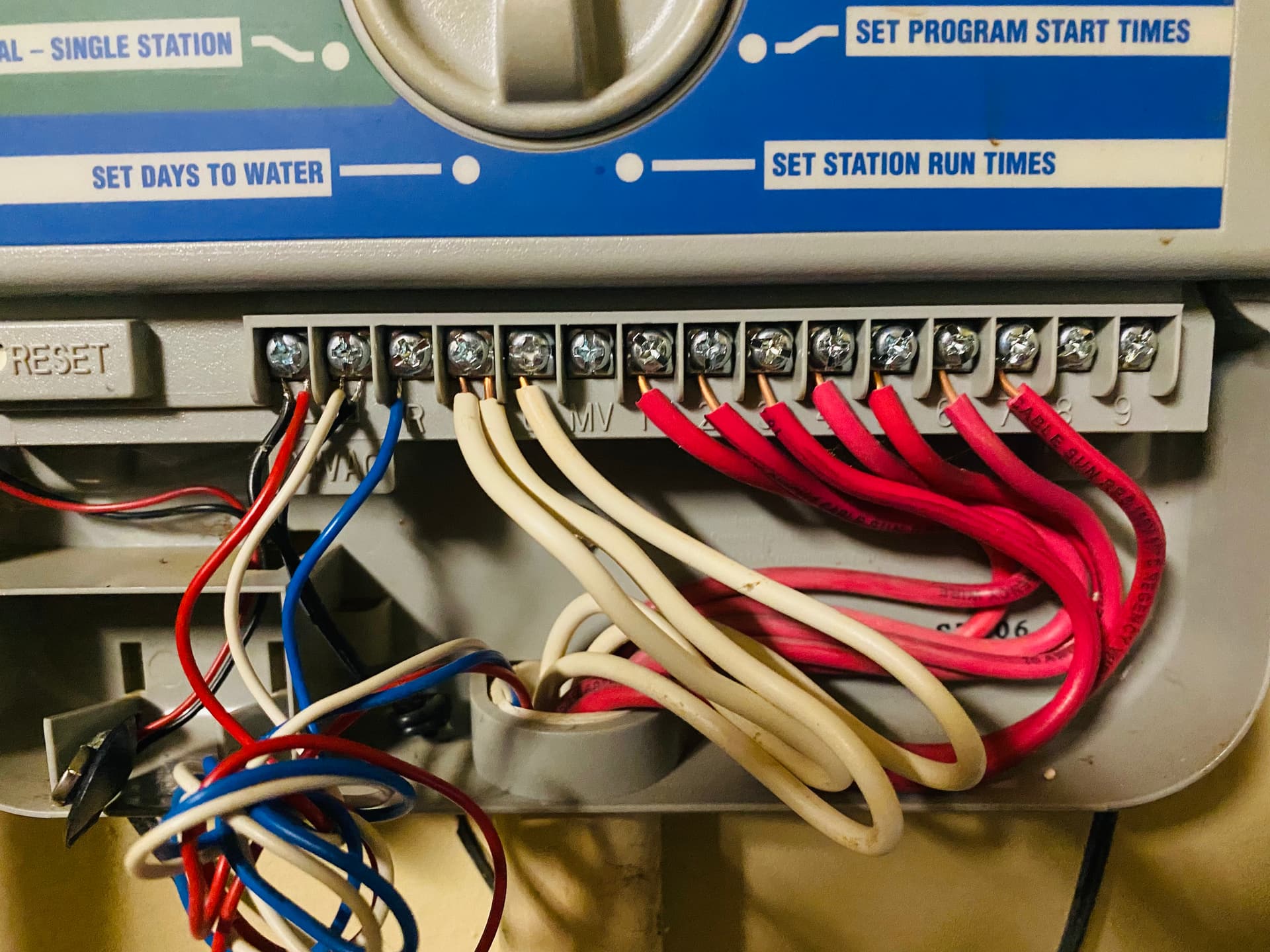
The labels from left to right are: 24VAC, R, RS, C, MV, 1-9
It is my understanding that your L-R labels/wiring translates to the following;
- 24AC + = Power positive
- 24AC - = Power negative. (It seems that they have a set of wires coming in that powers the unit and then another set that carries power to an accessory. )
- R = is the remote interface to operate the controller without standing in front of it
- RS = Rain sensor, in this case it looks like you have 3x wires in there and since 2x of them are white I think your rain sensor is the purple cable and the 2x white cables might be the common for pump relays?
- C = common, any valve’s will have their common coming back here. Since there are 2x it tells me that you either have 2x wire bundles or an active master valve.
- MC = Master Valve. this would turn the main water feed valve on/off at start/end of schedules.
- 1-9 = are your zones
Thanks everyone… I was able to connect the system. Now the only problem is one of the zones is not working… rest 6 are working fine… any suggestions?
One zone not working could be an issue with the valve itself or the wiring to it such as it came loose from the wire nut or not a good connection to the terminal. Was it working with the old controller?
HI Thomas,
As far as I can remember that station was working before… unfortunately i did a rookie mistake of not testing all the zone just before the controller changeout :(… I will try testing the wiring system… strange thing is when that station is activated, i can hear a click and water hissing at the valve but the sprinklers will not activate… tried turning the solenoid but that didnt help either…
Sounds like it could be an issue with the valve solenoid or diaphragm. If the diaphragm is failed or failing, or the solenoid plunger is damaged, it may not be opening enough to allow enough water to pass through the valve to pop up the sprinklers. Chances are, if you let it run long enough, you would see water around the sprinklers as it leaked out the wiper seals, but again, not enough pressure to pop them up.
1 Like