Hi, I have an electronic question.
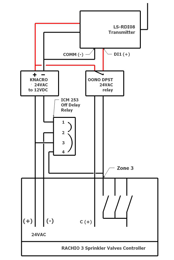
One of my Rachio zones is on a wireless transmitter. I have a Wireless controller that is triggered by the Rachio zone output, and sends a signal to a receiver board that drives the sprinkler valve.
The wireless controller can take either AC or DC input, so for now the Rachio zone output was connected directly to the Controller input.
But it turns out the controller would prefer DC, as the AC input is unreliable and tends to die after a while.
So I want to use a DC input on the controller instead of the 24VAC signal of the Rachio zone output.
I figured there would be two ways to do that.
1- Use a 24VAC to 24VDC converter like this 24AC-24DC
That would take the Rachio valve signal and convert it to DC for the wireless controller.
I tried it, but for some reason, the presence of the Converter makes the Rachio detect a valve error (output red) and cuts off the signal Anyone knows why adding the AC/DC converter would cause an error on the Rachio output?
2- Use a 24VAC relay, that will take the Rachio Output signal to close a circuit feeding 24DC to the controller input. ICM104
Or: OONO DPST
Before I try that I would like to know why solution one did not work to get a sense on whether the second one could work.
Thank you to anyone who could shed some light on this
The specification says “The AC to DC Converter Input voltage:24V(AC) Output voltage:24V(DC);Current:4A”. I presume the 4A is on the output size and if so, it does not say what is on the input. It seems most valves are 200-300mA when energized. I do not know what kind of current the transmitter draws nor what the loss is from the converter. This information may identify the issue.
Thanks,
Given it works when the rachio ouput goes directly in the controller, I assumed the controller was drawing a compatible amount of current.
So I assumed that would also be true at the input of the converter.
One possible issue is that the losses are so big in the converter that the converter draws too much power and that causes the rachio to shut off the output.
If that is the issue then the relay will work as it will draw very little.
So my question is whether anyone can think of another reason the converter creates the error.
I would not worry about it and leave it at AC. but if you really insist, maybe use a simple rectifier bridge and capacitor filter to smooth out the outputuu. The problem is that the initial charge of any capacitor in the system would draw more energy (and current, for that matter) to exceed the rachio max output.
you may still have the same issue during rush current stage. Also note that DC voltage is a little below the ac voltage times square root of 2, meaning a 24V AC will produce around 32-34V DC.
Thanks,
I dont have a choice, the Inputs using AC are dying after a while and the manufacturer is aware of the issue and suggested DC should not have the issue.
Testing DC on an input that no longer works with AC appears to work.
I am going to test the relay, that has very little Amp draw and should not trip the Rachio.
The AC to DC converter I bought converts the 27VAC of the Rachio to 24DC exactly.
got it. Yes, the relay path is the safest bet as it physically separates the two circuits, shielding each device from the other. Also, no inrush current (well, not large enough).
So the small 24VAC relay works great, when the Rachio activates the 24VAC zone signal, it feeds a 12VDC coming from the controller power supply on the controller input.
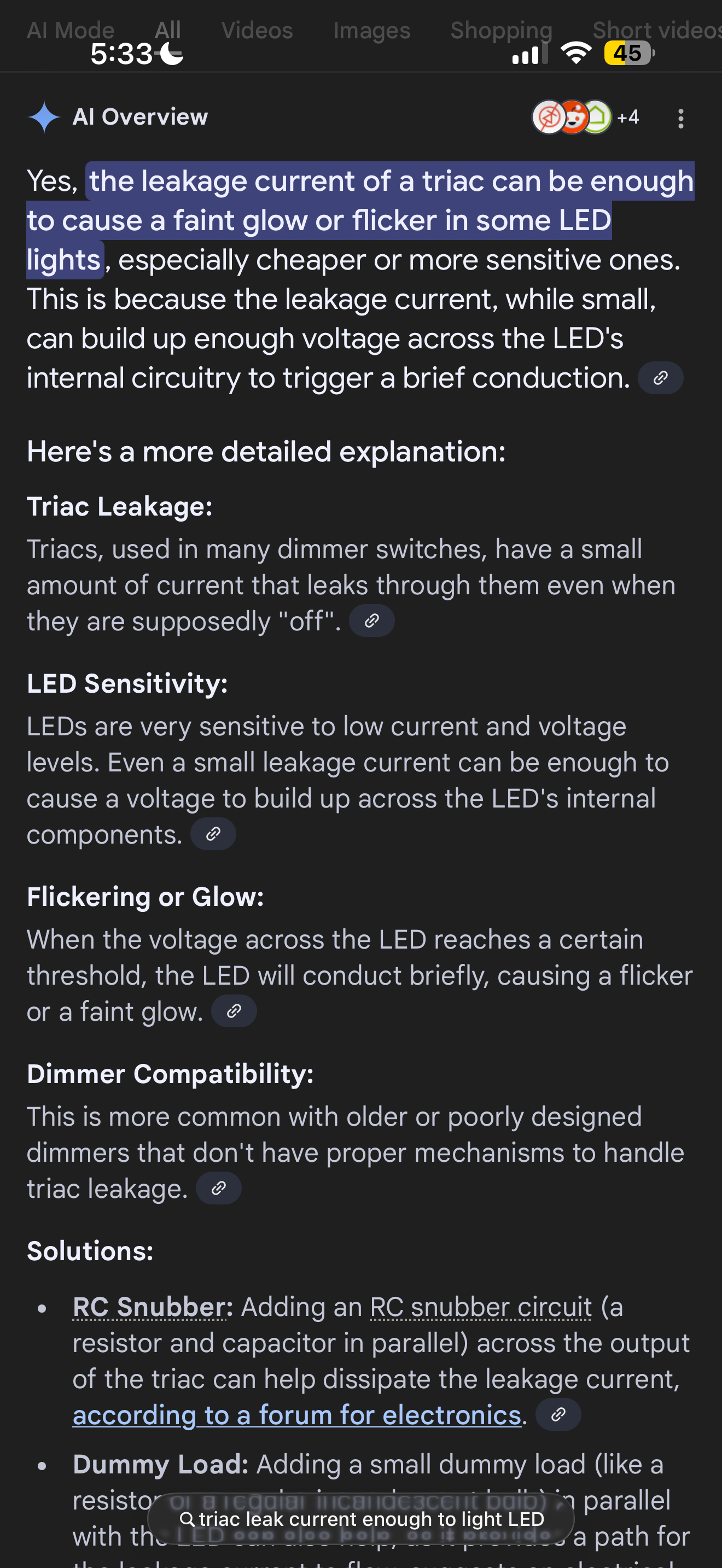
Now that relay has a small led, and I noticed the led lights up even when the zone is not activated, So I measured the voltage between the outputs common and the zone output when not active, and there is a residual 3.8Volts there…
Is that normal, and if so what is the purpose of it?
Is that a flaw in Rachio 3 (does everyone has that residual voltage on inactive zone outputs)?
Is that a defect of just my unit?
Appreciate if anyone knows or can measure the tension on some of their inactive zones.
Rachio uses solid state switching (triacs most likely) which can have residual currents flowing. The LED is most likely in series with a resistor and if the two have high enough resistance they can see enough residual voltage to open the diode gate forward and emit light, but faintly. Is the LED full on or faint?!
I can test when I get home. Do you see the same on other ports? As long as the relay is not humming or buzzing you are ok, there is too little current to energize the coil. Do you see those 3V while open or with the relay connected? What do you see open, what do you see with relay connected (all while zone is off) and what do you see on other off zones?
Well, good you asked, because other outputs do not have the issue.
It turns out the leak comes from a second relay also connected to the zone output in question ICM delay on break relay
That relay powers the wireless transmitter only when the zone is active, and keeps it alive a few seconds after it shuts down with a delay on break, to make sure the transmitter can send the close valve command.
So the leak comes from that relay and not the Rachio…
Maybe I need to look for a better one…
Regarding
“As long as the relay is not humming or buzzing you are ok”
Funny you say that, because what also alerted me is the relay was clicketing.
but I found out that depending on its orientation I could get the clicketing to stop…
So I mounted it in the silent orientation, and it is not getting warm… Fingers crossed
well that’s not peachy. The silent side is probably putting up more effort to throw the relay, I would say it is safe to assume this is no bueno. Can you possibly drive both devices through two relays driven by rachio? Got any specs on the relay? what is the coil current draw? any part number? As long as it is below 200mA you should be fine driving two relays. Got a master valve? Complicates things as it uses up yet more current…
it may not get warm, but it sure gets worn (out)…
LE: there is a way to limit the current draw, if the relay is wide voltage range (say 12-24VAC), you can drive them in series. Or use two 12VAC relays in series to drive the two devices separately. You’ _may_ need a power supply for the wireless whatever that is.
The thing is, because I am using a relay to only power the transmitter while the zone is active, I wanted a delay on break relay, so that the transmitter stays powered for 10 seconds after the zone becomes inactive, so there is time for a clean shutoff command to be sent.
Usually delay on break relays need a constant power source so they can maintain the output for a while after the trigger goes off.
The ICM253 was the only 24VAC relay I could find to do that.
Now that I am actually creating a 12VDC signal out of the 24VAC zone signal, I could use a 12VDC relay, but I have not found one so far that would take 12VDC power and a 12VDC (or 24VAC) trigger to close a relay AND have a delay on break.
Connect pin 4 of the ICM253 to Rachio (-) via an SPST relay driven by zone 3 and Common? this way you insulate Zone3 from the leaky delayed relay. That’s what I would do.