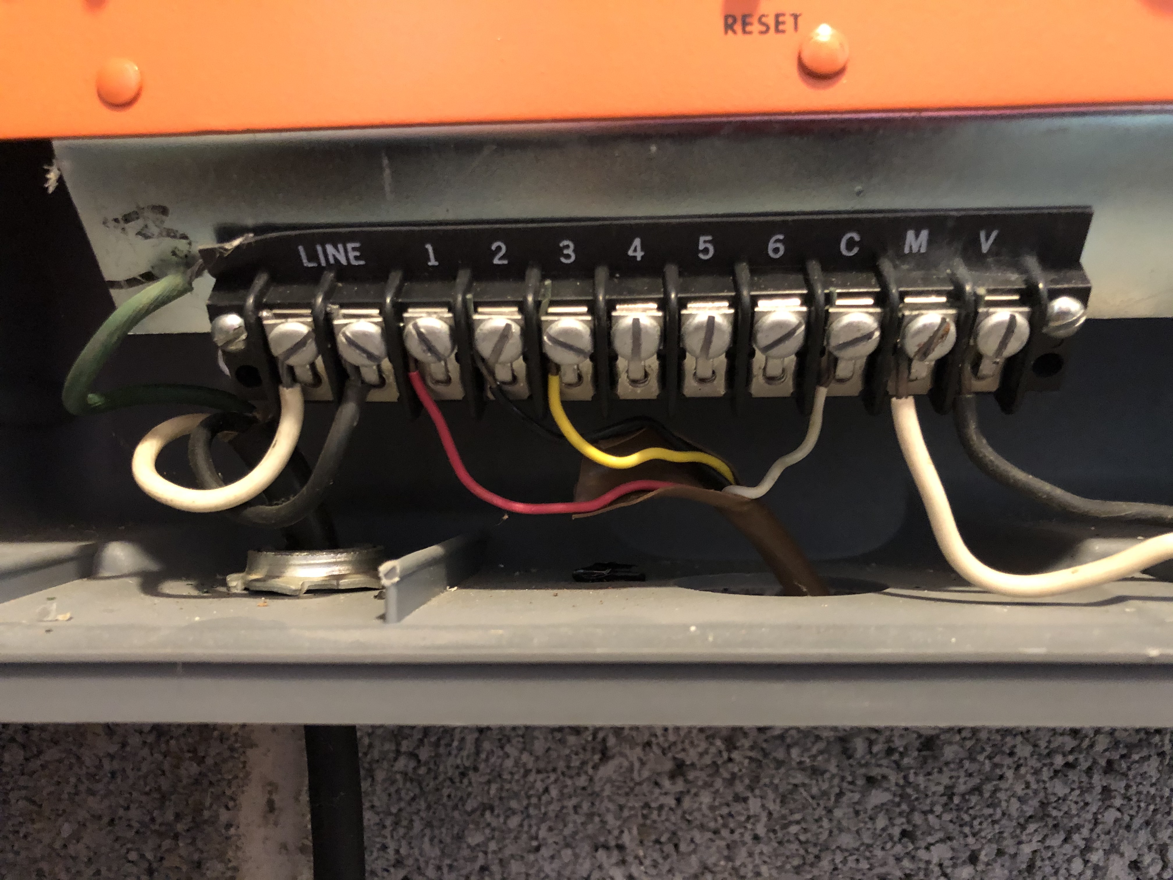
I’m trying to wire my 3rd gen controller from an old imperial valet controller. However there is a M and V wire on the old controller. No where can I find where the V wire goes?
Please advise.
Dave
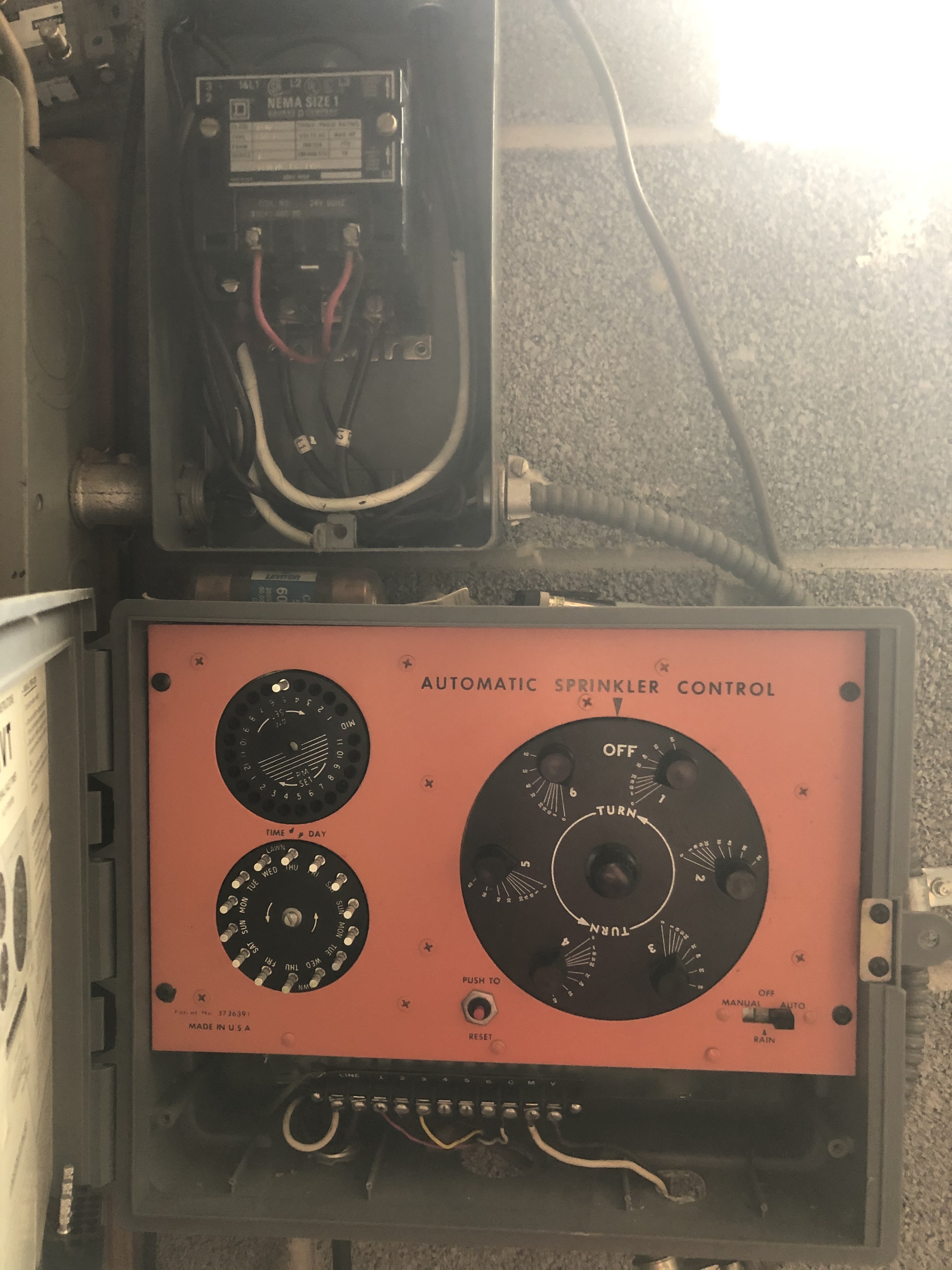
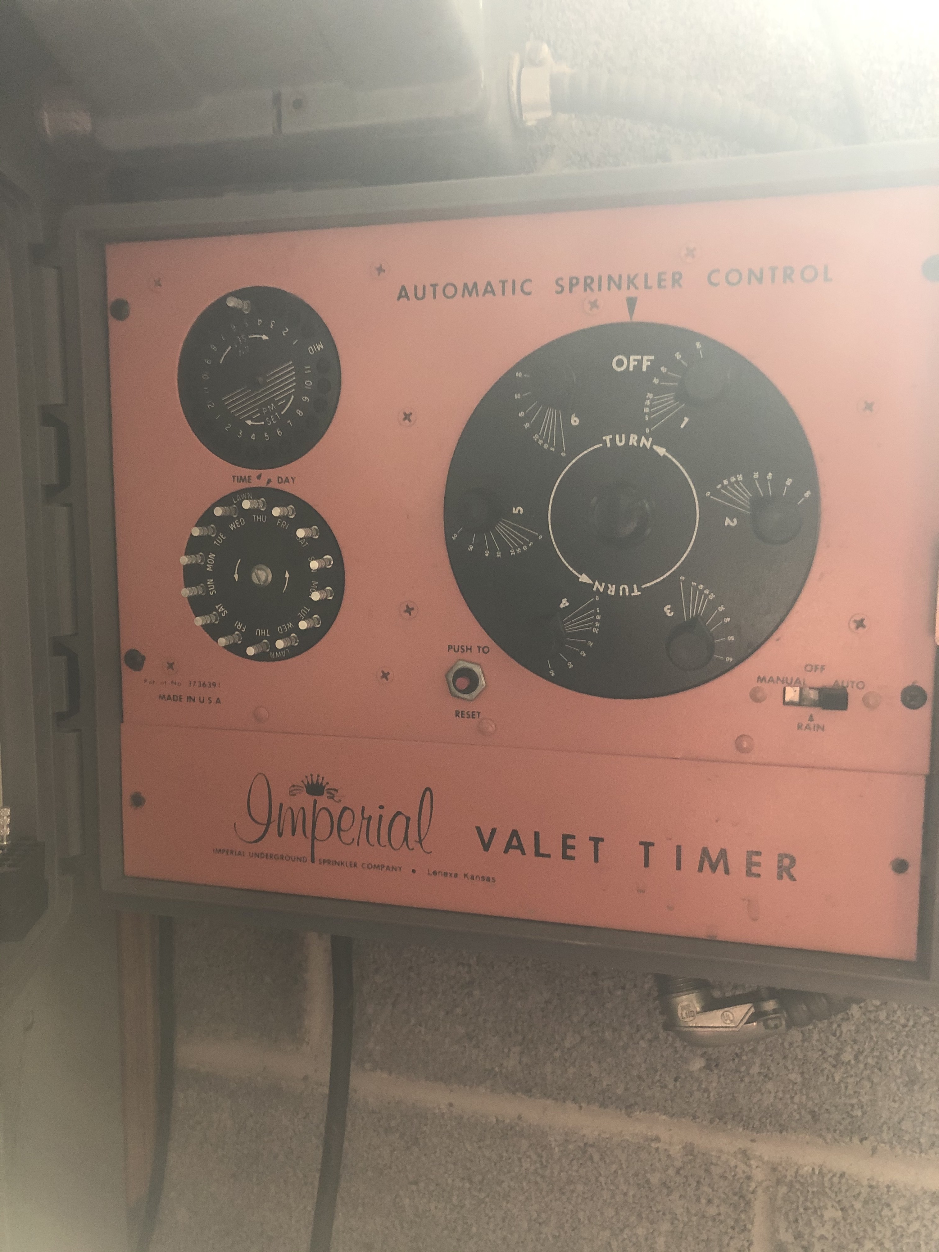
@videodave - any pictures of the wiring or system that can be posted. Was it working before?
I’d grab an ohm meter and measure the resistance down the V line to the Common line (best guess) to see if there is continuity. If no continuity, then I’d check with the M line. If there is no continuity, then it may just be a phantom wire that goes to no-where and can be abandoned.
Can the system be described - is there a pump start relay or a master valve in the system?
I’d also check the resistivity of a valve as I ran across a post on the internet about old imperial valet solenoids drawing lots of current. Do you know what valves/solenoids are in use?
Is there a rain sensor in the system? Is it in-line on the common wire?
1 Like
Hello, thanks for responding.
i did measure the wires, only when the timer goes to a zone the m & V wires measure about 28V AC.
I tried the M wire into the new 3rd gen M, then the V wire in the C, it caused an error. I tried the M & V wires into the 24vac, that caused an error.
I enabled then disabled the master valve wire in the settings, that didnt work.
No rain sensors.
HELP,
Dave
@videodave - what was the error message that was received? What happens with just the Common and zone 1 wire’s hooked up? Any error message then when zone 1 is run? I want to see if the existing solenoids pull too much current for the Rachio.
Looks like there is a pump start relay just above the old controller. Some pump start relays pull too much current for Rachio. I can’t make out the plate on the front of that device to see what load it pulls. One should aim for .35 Amp or less current inrush (from memory).
There are two ways to fix this if the pump start relay and/or the existing solenoids pull too much current for the Rachio.
-
Replace the pump start relay and possibly the solenoids with newer versions that don’t pull as much current.
-
Put a SPST relay between the Rachio and the high current draw devices (one relay per device) with Rachio controlling the relay coil and a separate higher capacity 24 VAC power supply being routed via the relay to the device.
It looks like both the M and V wires run up to the box above the controller. Do they both terminate there?
2 Likes