@Wedgie has done the same adjustment back in December 2018. He did not have any issues
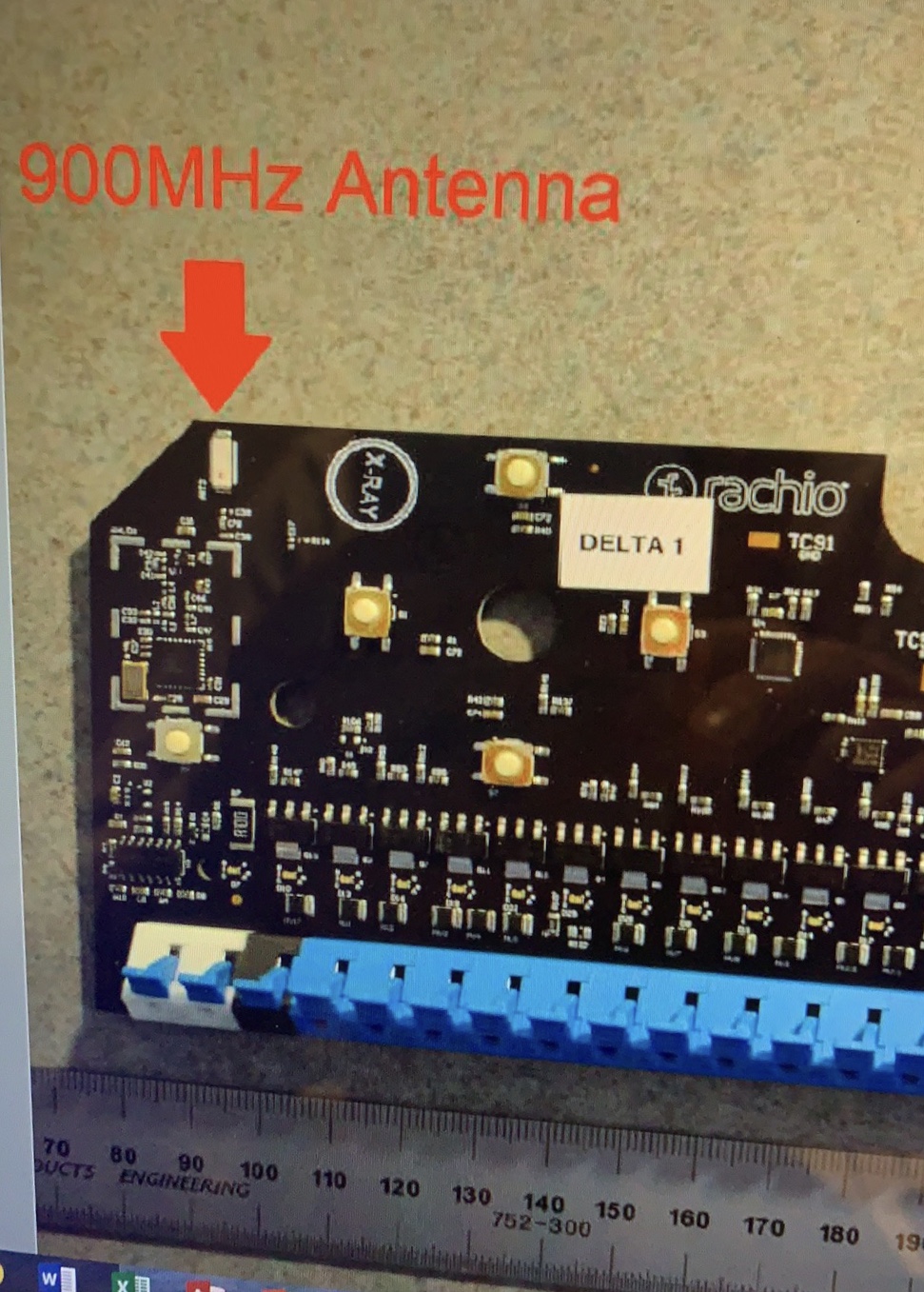
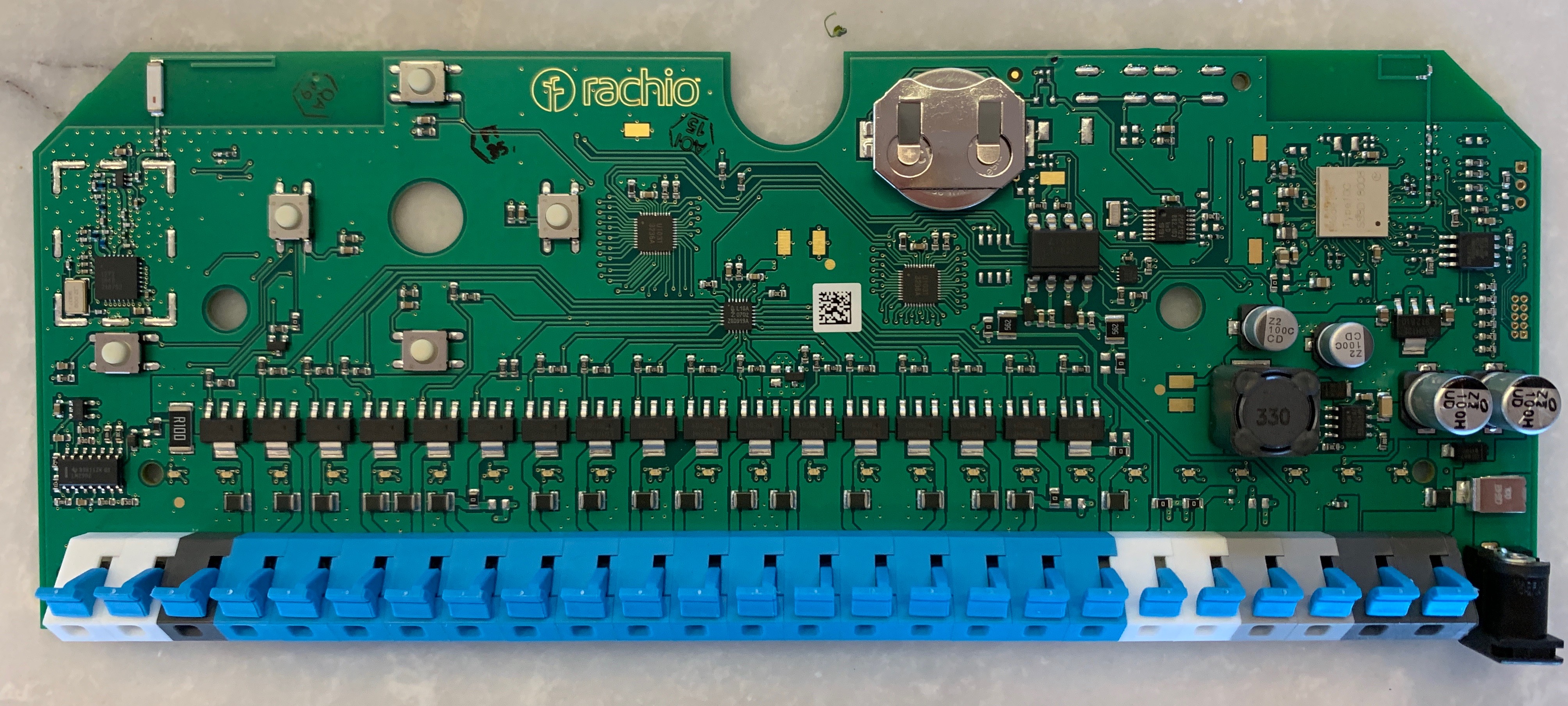
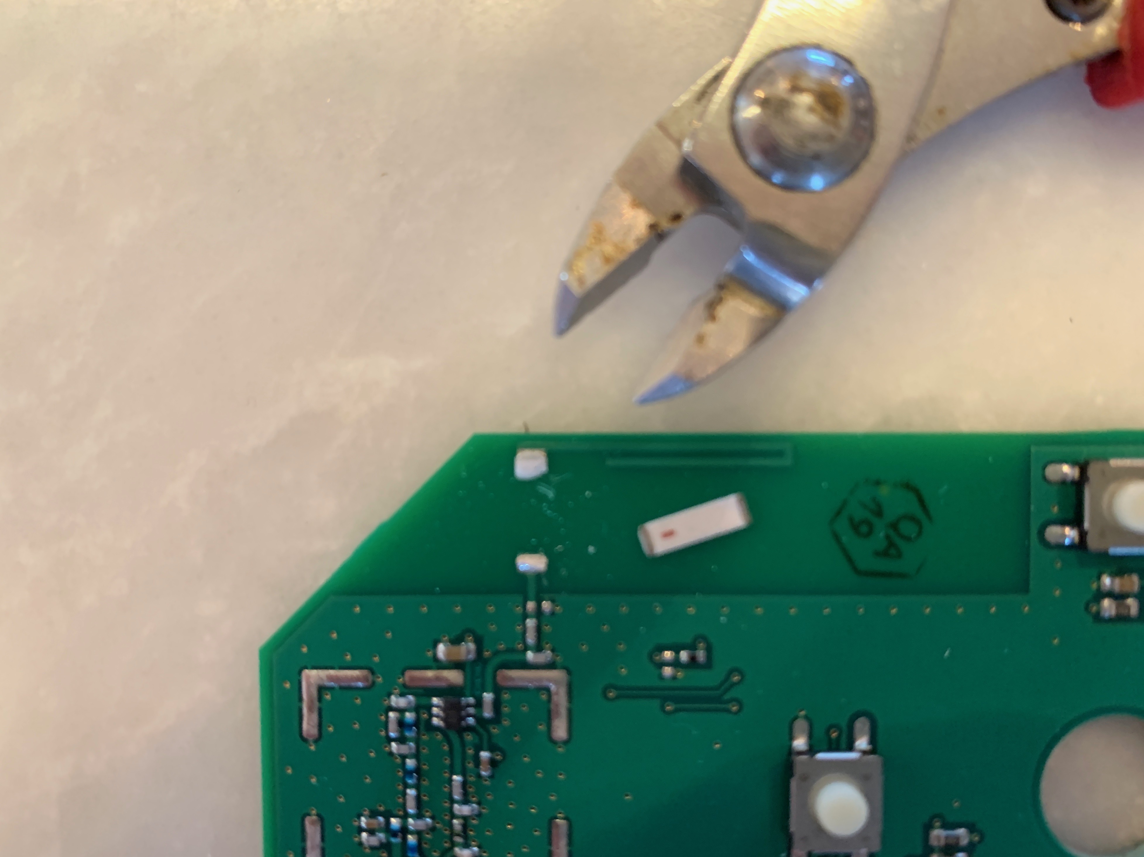
Antenna in this design is essential for a proper signal gain, you should not have any issues with your local authorities / cellular service. As an engineer I would steer away from cutting the parts of the board (preferring to use soldering instead), but it seems you’ve done a clean job.
I do appreciate you taking the time to document your attempt, it will surely be helpful to others in the future.
As an engineer I can also point out an alternative way to disable the signal, that will be easy to undo in case Rachio ever develops a firmware fix. Unfortunately, one would need to be comfortable with putting a blob of solder onto the board.
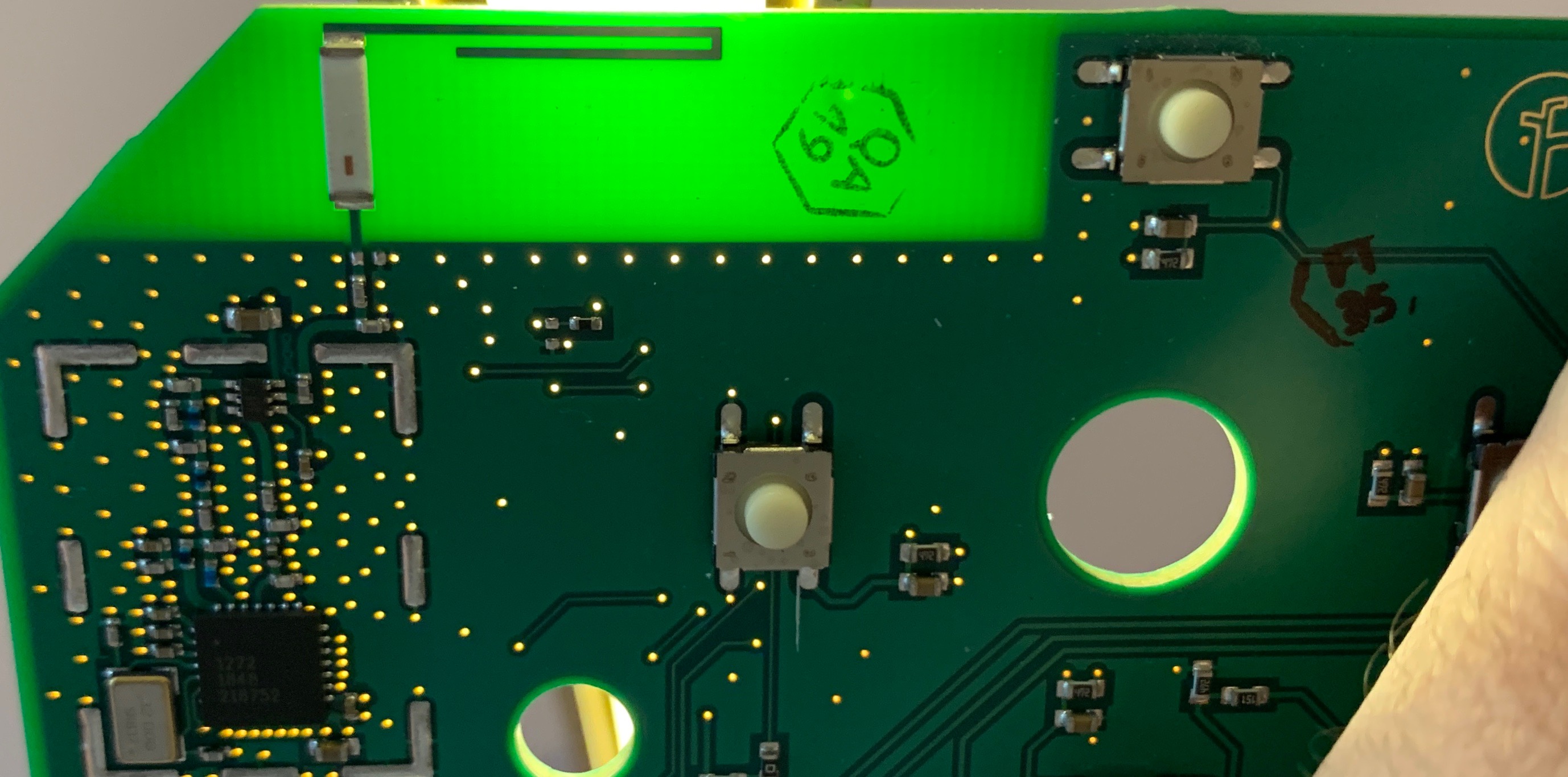
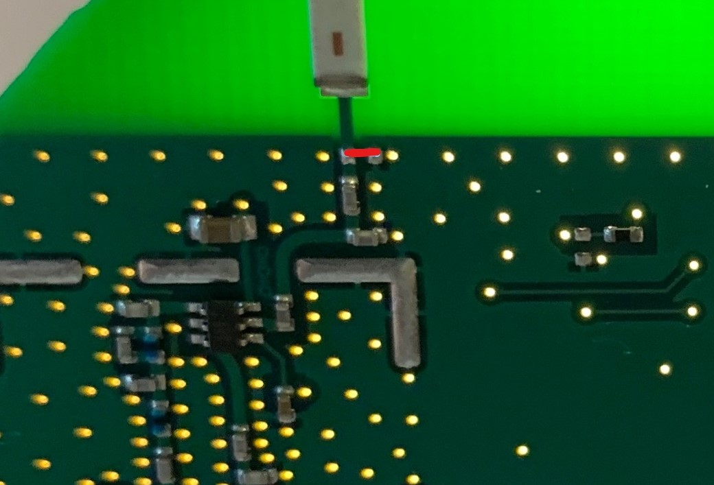
Between the antenna and the rest of the circuit, there are two pads, meant for a load matching resistor, which (when shorted) would effectively dump the signal into the ground, thus preventing it from being transmitted. Using a bit of solder and/or a short bit of wire, these pads can be bridged, thereby temporarily disabling the radio signal. Later on the bridge can be removed, restoring the full functionality.
I’ve highlighted the connection which would disable the signal with red:
Anyway, just wanted to propose a less permanent solution which should work just as well until manually undone. Good job again @hcornea for sharing your work, it’s definitely a more universal solution to what I’ve proposed here.
OK, so we’ve got two alternatives, both of which work. Out of curiosity, what about alternative #3, non-invasive, no patch, no surgery—why not just put a Faraday cage around the thing?
Kills signal
No warranty issues
Easy to undo when a FW fix comes through (this s/be able to be done in FW)
It’s an option, I’ve brought it up a few posts ago in this very topic:
This approach can make a difference, but there is simply no grantee that the signal would not escape. You also run into issue of potentially blocking your wifi signal from getting to your controller. This approach is perhaps better than nothing, but does not rate highly as others in terms of effectiveness.
So if you remove the antenna as outlined in the previous posts, wouldn’t this affect the WiFi connectivity? Or does this have a separate antenna for that?
Hi. This is great thanks and I’m ready to try it. But I can’t get the case off the circuit. I’ve unscrews the two screws but there’s something h else holding it down. Please assist.