Sorry, I am catching up on the thread from the wrong end, I fear I’ve skipped your original write-up.
May I ask if the zone fault error you’ve described, is primarily dealing with the master valve or a random zone?
I think what you would try is connecting all of the commons from your two controllers together. Basically add a wire bridging a common terminal on one controller to the common terminal of another.
Do you have your schedule set so that both controllers may end up running at the same time?
The issue may be that when one controller is active (#2), the second controller is completely disconnected from the load.
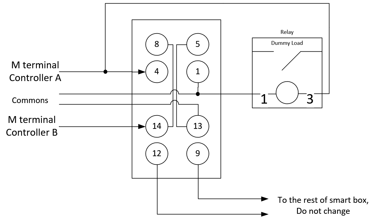
Try hooking up one of your new relays as a dummy load to terminals 1 and 4 of the left relay within your old munro smart box. Please note that the relay should not have any load attached, meaning that terminals 2 and 4 (or 5) of the new relay should not have anything attached on the new relay.
Step 1: Creating a bridge for the commons: Using the OLD/orginal setup and the new Relay Setup I created a bridge between the two commons: no change / still get the master zone faults in the orginal setup, and just the relays activating without the pump turning on.
Step 2: Question about your instructions here:
“Try hooking up one of your new relays as a dummy load to terminals 1 and 4 of the left relay within your old munro smart box. Please note that the relay should not have any load attached, meaning that terminals 2 and 4 (or 5) of the new relay should not have anything attached on the new relay.”
My question: I am assuming that I am using the new relay rig/diagram for this test? And if so, with the left relay acting as a dummy load, should the right relay still be wired up according to the diagram or be completely disconnected? Or am I using the original Munro setup and just putting the load on the left relay as you stated?
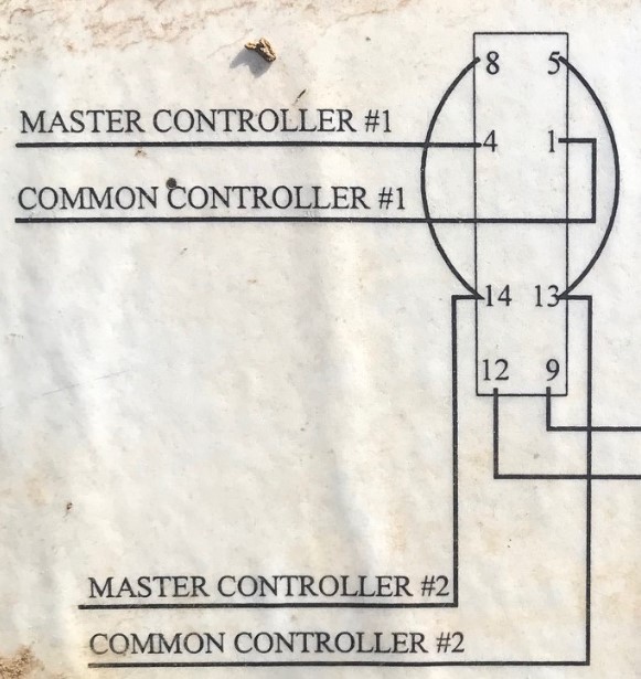
Sorry about confusion about the dummy load, the idea is to use old (original) setup and add to it one of the relays from the alternative setup to be connected to terminals shown on the cover picture you’ve shown earlier
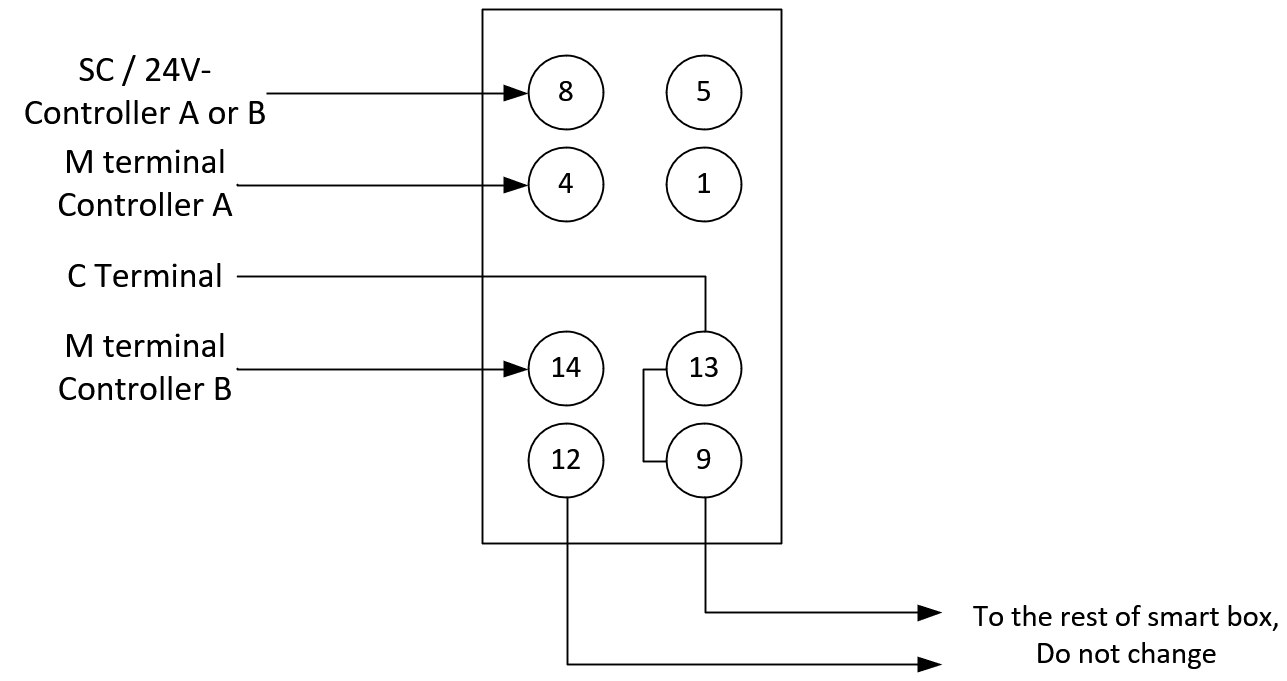
Option A would be to add the new relay you’ve bought to be in parallel with Controller #1 (A), basically terminal 4 would have two wires connected to it, connection can be made elsewhere using a wirenut or something similar.The dots on the drawing indicate wires that are connected. Connection can be done at the terminal screw or elsewhere via a wirenut.
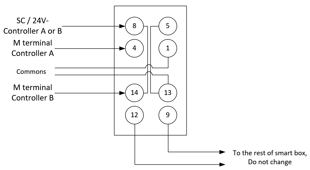
Option B does not require a new relay to act as a dummy load, but does require an additional wire to run from one of the controllers (which ever is easier) wire should come from SC terminal (in case you have a Gen 2 controller) or 24V- terminal (in case you have Gen 3). This configuration is a version of a setup known to work (link)
NOTE! I’ve accidentally left the original jumper from terminal 14 to terminal 8 in place in below diagram. For this option this jumper should be removed (see the post below).
I’ve edited the drawings to minimize amount of changes. Just keep in mind that the right side of the relay (terminals 5,1,13 and 9) are all commons and can be interconnected elsewhere.
Wow - thanks for all this detail! I think I will try Option A. Conceptual I think I see what’s going on but
I have 3 questions that I think somehow all tie together:
From the question about the dummy load instructions - I see you mention terminal 4 twice (to connect it and also not to connect it). Can you clarify that for me?
I have Gen 3 controllers - and I am not familiar with ‘SC’ and ‘Commons’ in the diagram. Are these just the C wires from each controller?
In your diagram - as you say ‘The dots on the drawing indicate wires that are connected’. I am not sure I see dots on my display for option A. I am not sure where the new relay should be on that diagram. I have a feeling that has to do with my first question but I can fully wrap my head around it.
Sorry, when posting updated drawings, I’ve mixed Option A & B diagrams. You originally observed Option B diagram for option A description and visa versa.
SC terminal is a terminal on a Gen 2 controller. Gen 3 has it labeled as 24 V - terminal.
Commons are lines connected from any available C terminal, in case you commons from two controllers tied together. (C terminal of one controller connected to C terminal of another).
Note that you can get away with just one common wire, if you move the original jumper from terminal 5 to terminal 9 and use original common hookup on terminal 13 (Labeled common controller #2).
Update: Please note to remove original jumper from terminal 14 to terminal 8 with the Option B configuration. I’ve accidentally left it in during my write-up.
Thank you for the clarification on the SC with Gen 2 and the common lines. I am tracking and ready to go.
To make sure I understand the correct options - I didn’t want to have to run a new wire and conduit as I did just that to increase the guage for my master value wire. While I do have a couple spare solinoid wires in my boxes/controllers, I fear the voltage drop will be too large. So what is the version that will not require me to run any extra wires for that SC/24V wire? Is that this one:
correct.
By the way. Power required via 24V- terminal is at most equal to a regular zone line. In case you have a spare zone wire available, do use that, it will be more that enough.
Update: I pleased to announce that the surgery went well - and more importantly, I think this setup (the last image) WORKED! I manually switched on 10+ zones on both controllers - and I did NOT experience a single master zone fault!! I hope I am not jinxing it as I post this as I will test it with schedules and more manual runs tomorrow. Fingers crossed!!
Very Interesting developments on this end - good news and bad news. Good news: I have manually run the zones 10 to 15 times - all WITHOUT zone fault errors! Bad News - strange master fault error on a scheduled items that doesn’t exist.
BEFORE I FORGET: @franz 1. I think @DLane and @Gene deserve another accolade on the support site beyond ‘Power User’ with their MacGyver-like skills! They have been fantastic as I have been fighting this issue for years. I can’t thank them enough for sharing their experience with me in a way that I could act on it! How can we buy someone a drink through this support tool? 2. I do have a FIRMWARE question below that may require your insights / considerations.
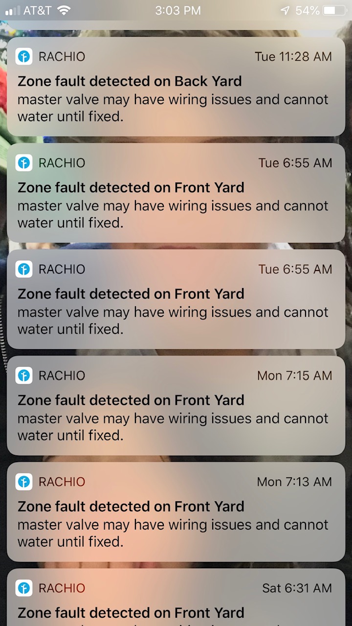
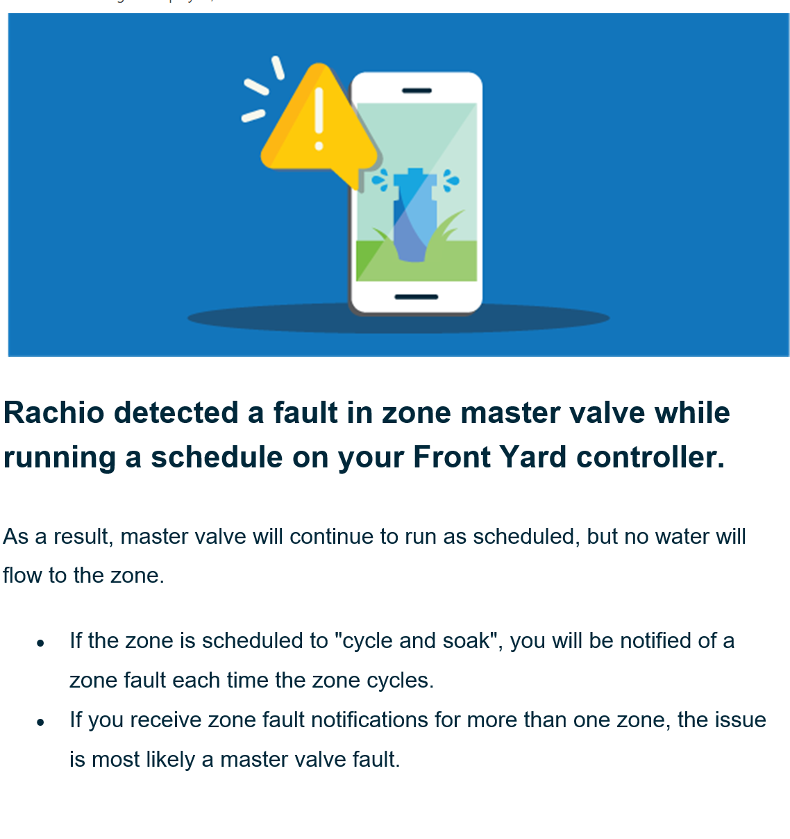
To everyone: I did discover a FAULT error with a ‘scheduled’ item - but this is strange and I am not sure this is related to the two controller issue with the Munro box. I woke up to seeing this in my inbox:
I thought that was strange as I don’t have any schedules - as it references an 11:30 pm schedule. So I checked both controllers - and to prove that I am not going crazy. Here is the Front controller:
Here is the Back controller:
Puzzled, I started looking at comparing both controllers - and noticed that the FIRMWARE on the Front controller (that generated the master fault error) was NOT the same as the back controller. So I updated the FIRMWARE to make sure they are in synch. So I am wondering:
Could the FIRMWARE have an impact on generating these fault errors? That’s the biggest question I have - and obviously can not answer.
How do I know if there is a ‘hidden’ schedule in one of the controllers? I used to have many scheduled items in these controllers (alternating so they would not conflict/both be running at the same time) in a Gen 1, then I migrated them to Gen 2 and then Gen 3 (all to try to troubleshoot this). I kept the schedules in place and finally deleted them on the Gen 3 to try to trouble shoot.
Way forward: I plan on 1) adding a new schedule item to both controllers and then delete them - to see if that cleans up the invisible scheduled items 2) Add a couple new schedule items, not using old times, to continue on the great work above by @Gene and @DLane.
@AngryIrrigationMan Can’t comment on what exactly could have caused the erroneous email, my guess it likely got queued some time ago (have you ever had 11:30PM schedule?) and just got out to you. Wouldn’t worry about it too much, unless it happens again. Does the error show up in the history tab within the app / website?
Great idea about checking the website as I forgot about using that for admin features in today’s app-centric world! And yes - I did have a schedule at that time as some point.
So on the website, I did not see any other schedules listed either - BUT I did see that it had one of my prior controllers there. So I deleted that just in case that may cause any confusion. I guess I’ll wait to see what happens at 11:30 pm tonight!
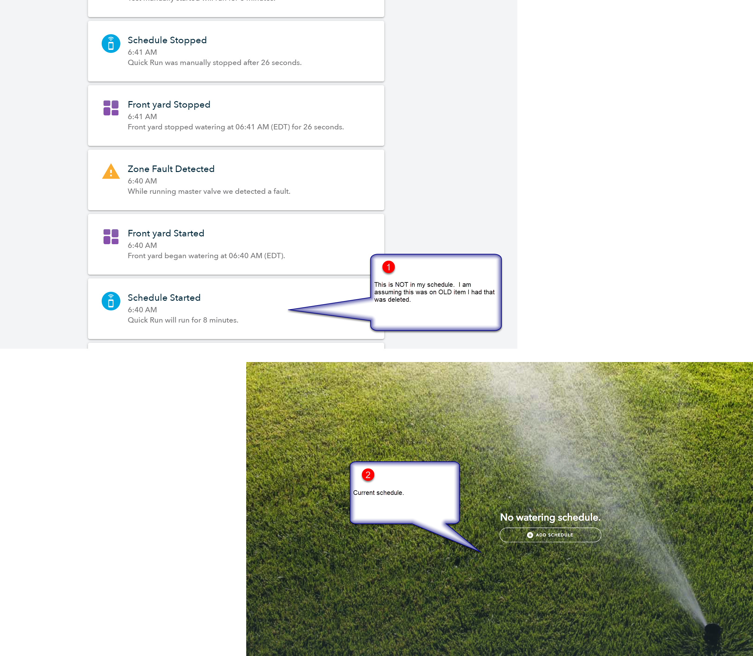
To answer your other question - yes, it shows that I have many scheduled items running! Very strange indeed.
Darn - I just recieved another zone master error while manually testing. Looking at the History - I think the controller is running old schedule - while I was manually testing it - even though there are none scheduled / showing on the GUI.
I will research this more - but I may just wipe the controller / set to the initial factory default settings (I assume I can do that) and hope that will delete these hidden schedules.
Note: I think this is a different issue that the relay configuration above. Let me do some more tracking and I’ll keep everyone posted.