I’ve got 18 zones, and have successfully got a 16 zone Iro up and running on 14 of them, and am just installing an 8 zone Iro for the remaining 4. I’m getting ready to wire up a relay to control the Master Valve and Common lines, and just wanted a quick sanity check; I understand that even if you’re an electrician you’re not -my- electrician, but I’m hoping some intrepid DIY-er will tell me if I’m doing something stupid.
The logic here is that if the Iro 1 master valve is powered, the (normally open) Iro 1 Master Valve and Common will be switched on, otherwise the (normally closed) Iro 2 Master Valve and Common will be switched on.
Thanks for any insight you can offer!
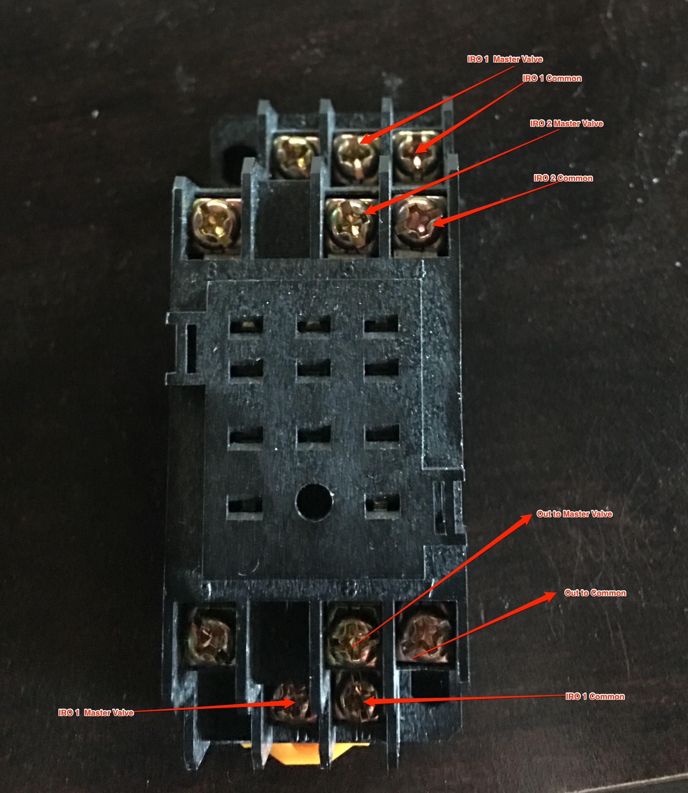
Edit – oops, my labels came out a little small… Here’s what they should show-
Row 1 – Input from Iro 1 Master Valve and Common
Row 2 – Input from Iro 2 Master Valve and Common
Row 3 – Output to Master Valve and Common
Row 4 – Iro 1 Master Valve and Common (to activate the relay)
Thanks for the reply! I did look at that page, actually. My problem is that the illustration didn’t make any sense to me (I don’t understand what the left relay is doing with no power to the relay terminals). Admittedly, I don’t know anything about relays other than “hey this looks like a DPDT switch that’s toggled when power is applied”. The photo on that page (which is wired differently than the illustration) makes a lot more sense, but it appears to assume I’m going to wire an independent power source for the master valve.
Understandably, when I emailed support they told me to hire an electrician (I’m sure they don’t want the liability), but unless I’m completely misunderstanding, it seems like it can be easily done with a single relay wired as above, but again, I’m hoping if it can’t, someone can tell me what I’m missing.
Alternatively, I’d be perfectly happy to use two relays and wire it as shown in the illustration if someone tells me I’m wrong and that they’ve got it working fine wired as shown.
Edit – just saw your edit… lol. Yeah, that’s where it lost me.
Yes, upon further review, I think that page is lacking.
Looking at your setup, it appears you have Rachio 1 (R1) on the normally closed (NC) contacts, and Rachio 2 (R2) on the Normally Open (NO) with the master of R1 controlling the solenoid.
Thus, when R1 turns on, the relay will activate and switch to the R2 master wiring (NOFC), and thus disconnect the R1 master power.
A cursory review would suggest swapping the coil wires to R2 and this may work. However, there are likely some potential issues that I am overlooking currently.
Good catch – it looks like I inverted the normally closed and normally open contacts. I’ll either reverse those or use the other Iro to control the solenoid.
Yes, there are definitely some potential issues if both controllers tried to run a zone at the same time, but I hope to avoid that by keeping their schedules to alternative days.
Okay, I’ve got it hooked up as above (but reversing Iro 1 and Iro 2 on the top connectors) and it all appears to be working so far. Obviously this is a ‘do at your own risk’ kind of thing tho, if anyone else is inclined to try it.