@emil Any thoughts about wiring the Hydro Rain HRC-100 for the Gen 3? Mine’s throwing rain alerts every few seconds…
Thanks 
@emil Any thoughts about wiring the Hydro Rain HRC-100 for the Gen 3? Mine’s throwing rain alerts every few seconds…
Thanks
I had a similar issue with my wired sensor. I didn’t notice the 24 VAC + and - terminals that are now used in place of the common for sensors.
Can you post some wiring photos? Thanks.

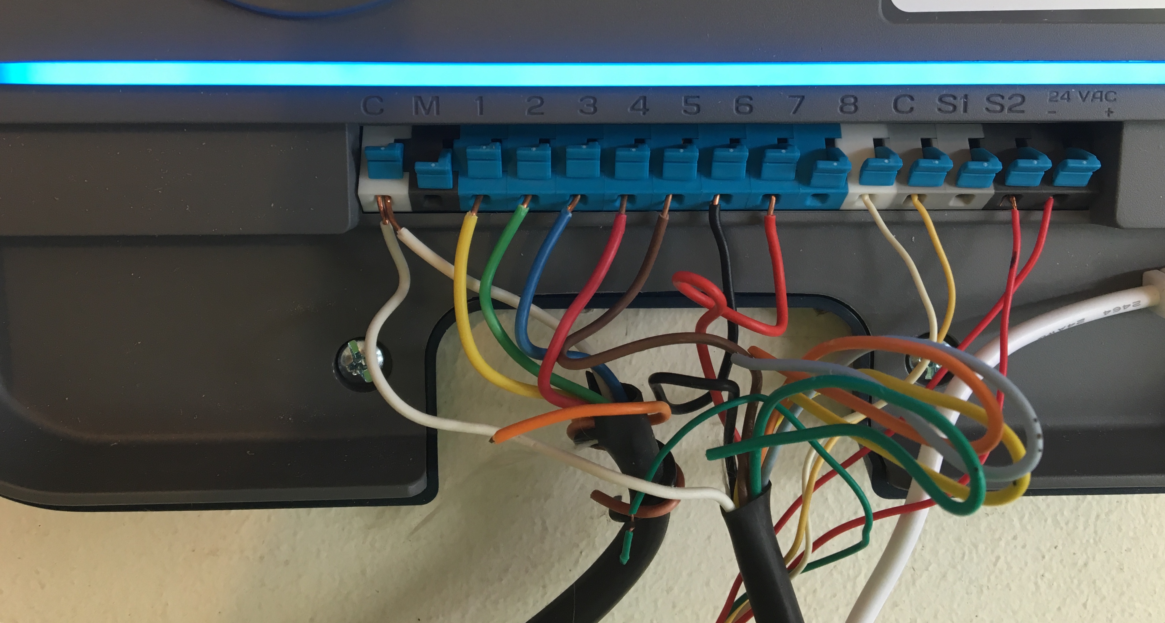
Looks like you just need to move the thin white cable connected to the ‘C’ terminal next to zone 8 to the 24 - terminal next to S2.
While making adjustments, I would also move the second common thick white wire from the leftmost C terminal to newly available C terminal next to zone 8. This way you have less chance of connector fatigue in a long term. Idea is to have just one thick white cable connected to each individual C terminal.
Cheers,
Gene
Why do I even try…
I need to stay in my lanes.
@Bobo1015, would you happen to have a picture of your working sensor’s wiring? I have the exact same setup and cannot make it work based on @Gene’s recommendations.
Out of town for a few days, sorry…
Can you post a picture of your setup? It is not just any white wire that belongs in the 24- terminal, but the one that is part of white, yellow and 2 red cable bundle.
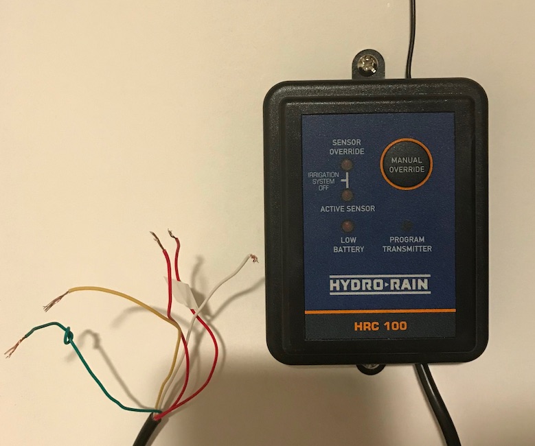
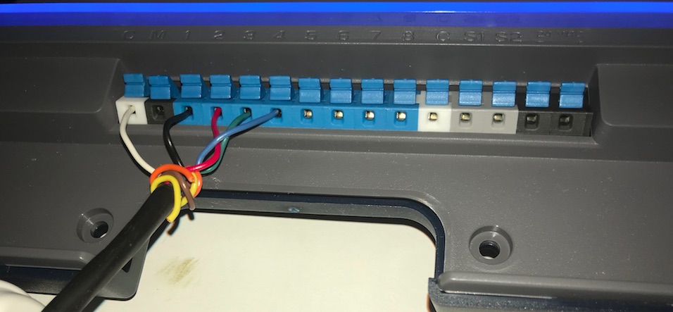
@Gene, please see below. It’s a simple 4-zone setup. The sensor is not connected in the picture.
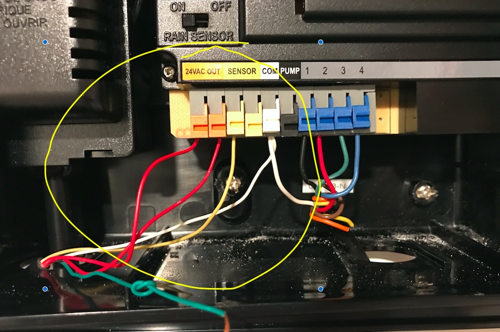
And this is how it was wired to the original Controller:
@ProjektR - at the risk of trampling @Gene 's great work here is what I’d try:
I’m wondering if the White wire had a good connection as that is what I’m trying to accomplish by twisting them together.
Are any of the lights illuminated on the Hydro-Rain in this setup?
If the above didn’t work, then one could try putting the White wire in the C terminal by itself.
Thanks for the pictures! Helps tremendously.
@Dlane is right on the money, I do not think that it will come down to connecting the white cable to commons (it belongs to 24 vac- as correctly indicated by step #5).
P.S. Here is an official diagram on how to hook up this kind of sensor:
Thank you @DLane. I will give this a try tonight. I had the sensor originally wired as such:
White -> C
Yellow - S1
Red 1 -> 24V1
Red 2 -> 24V+
It picked up the sensor, but I kept getting constant notifications about the sensor being Active/Inactive all within the same minute (the log is not granular enough for me to see if there was any delay). Safe to assume something was wrong :). I will report back.
@ProjektR - I think if the White wire is moved to 24 V- like @Gene commented on or in the directions it will be good to go. If not, @Gene and I will wrestle it to the ground - so far we are undefeated! (But who’s keeping score besided @Gene and me !)
I am ![]()
![]()
![]()