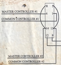
To shed some extra light on what I mean, you would be working with the relay within your smart box, particularly this one:
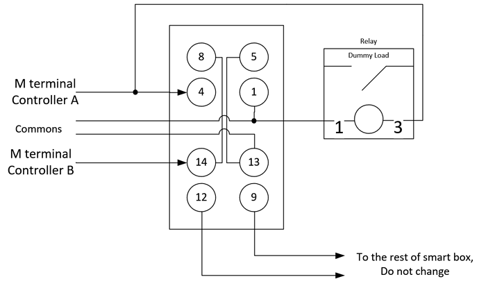
Option A would be to add the new relay you’ve bought to be in parallel with Controller #1 (A), basically terminal 4 would have two wires connected to it, connection can be made elsewhere using a wirenut or something similar.The dots on the drawing indicate wires that are connected. Connection can be done at the terminal screw or elsewhere via a wirenut.
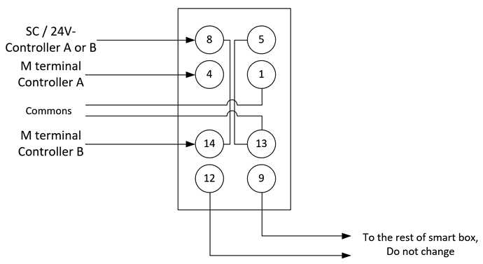
Option B does not require a new relay to act as a dummy load, but does require an additional wire to run from one of the controllers (which ever is easier) wire should come from SC terminal (in case you have a Gen 2 controller) or 24V- terminal (in case you have Gen 3). This configuration is a version of a setup known to work (link)
NOTE! I’ve accidentally left the original jumper from terminal 14 to terminal 8 in place in below diagram. For this option this jumper should be removed (see the post below).
I’ve edited the drawings to minimize amount of changes. Just keep in mind that the right side of the relay (terminals 5,1,13 and 9) are all commons and can be interconnected elsewhere.


