2 Controllers with Munro Smart Pump Relays. Does it work? Yes / No?

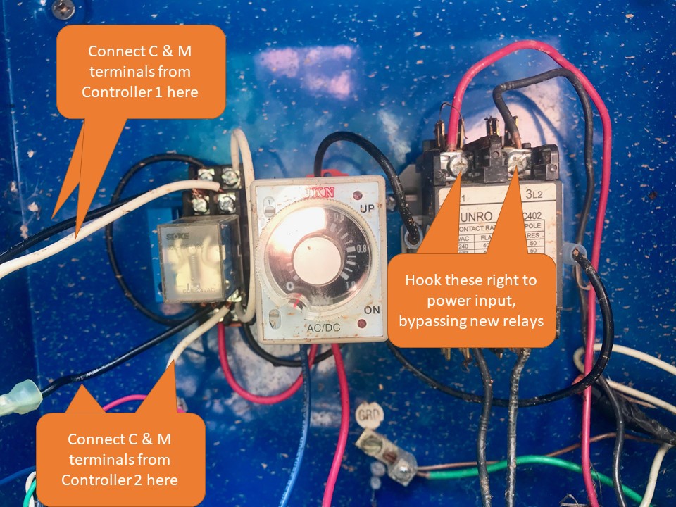
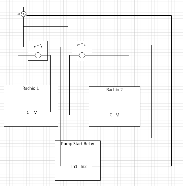
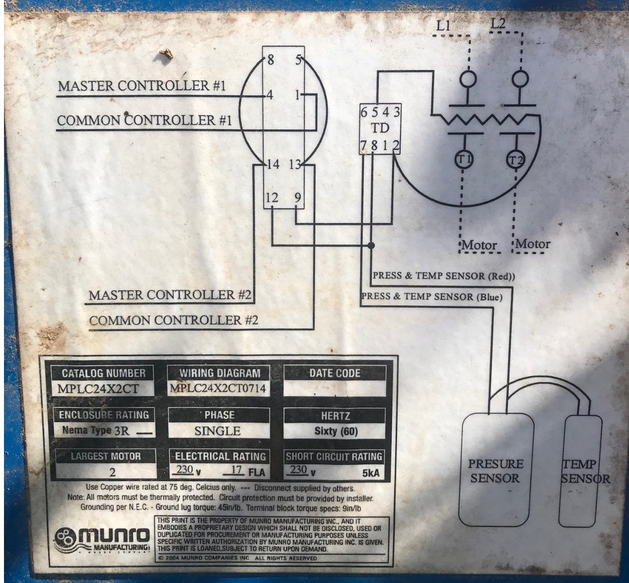
I can’t seem to find a definate answer to the following questions - and wanted to see if I can get Yes/No answers - and any other suggestions regarding the Munro Smart Pump relay that allows 2 controllers to control a single pump/source. The Smart Pump performs other great features to save your pump too but I don’t want to get off track here.

Yes or No: Does Gen 2 or Gen 3 controllers work with Munro Smart Pump Relays without showing zone fault errors? (ie two controllers connected the Munro smart relay)

Yes or No: Has Rachio product / support / dev actually tested with the Munro Smart Pump Relays?

Yes or No: Has anyone fixed / found a work around for Zone Fault messages when two controllers are connected to the Munro Smart Relay Pump?

*** Background ****
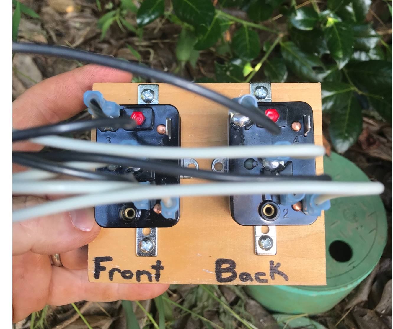
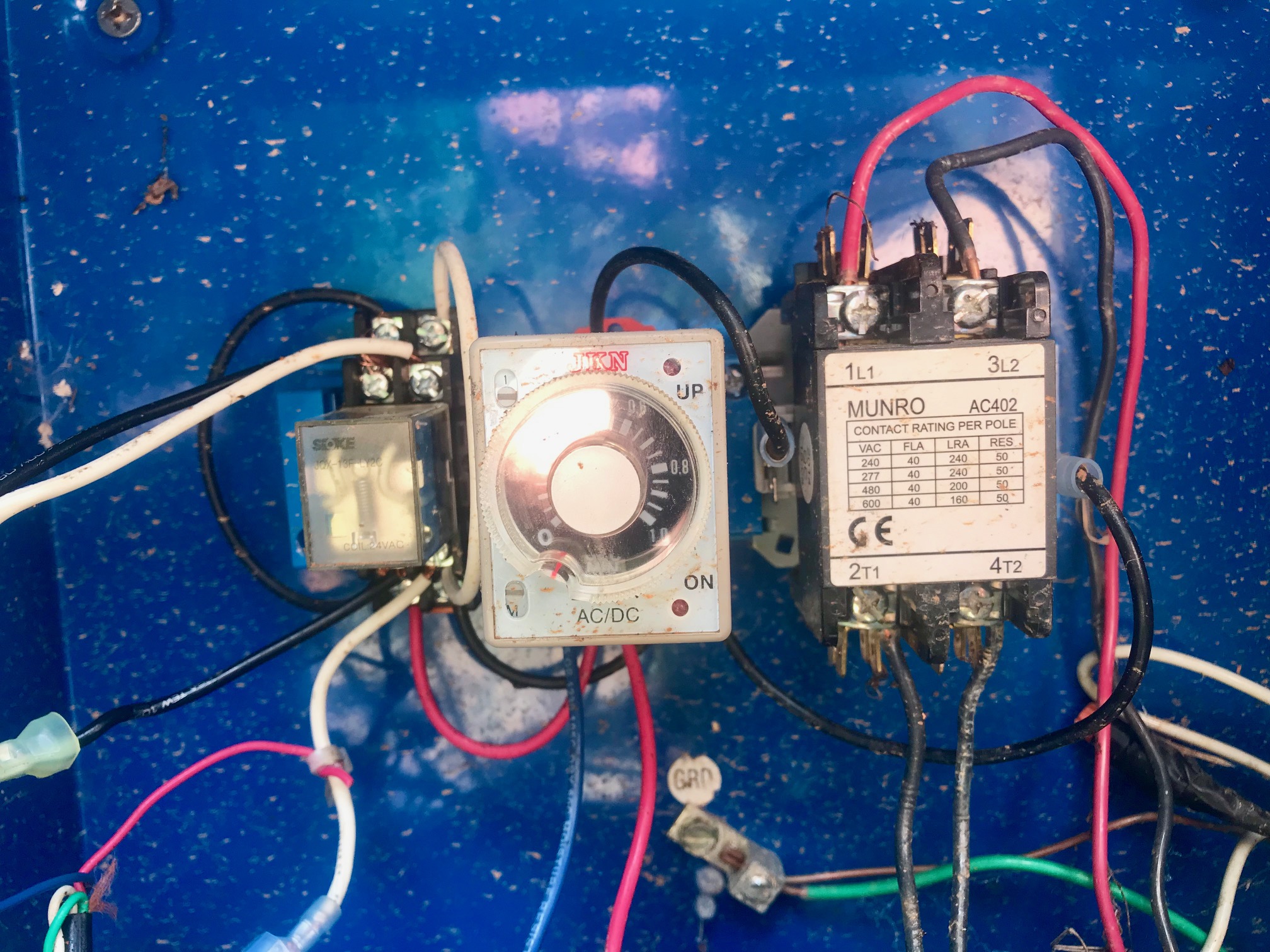
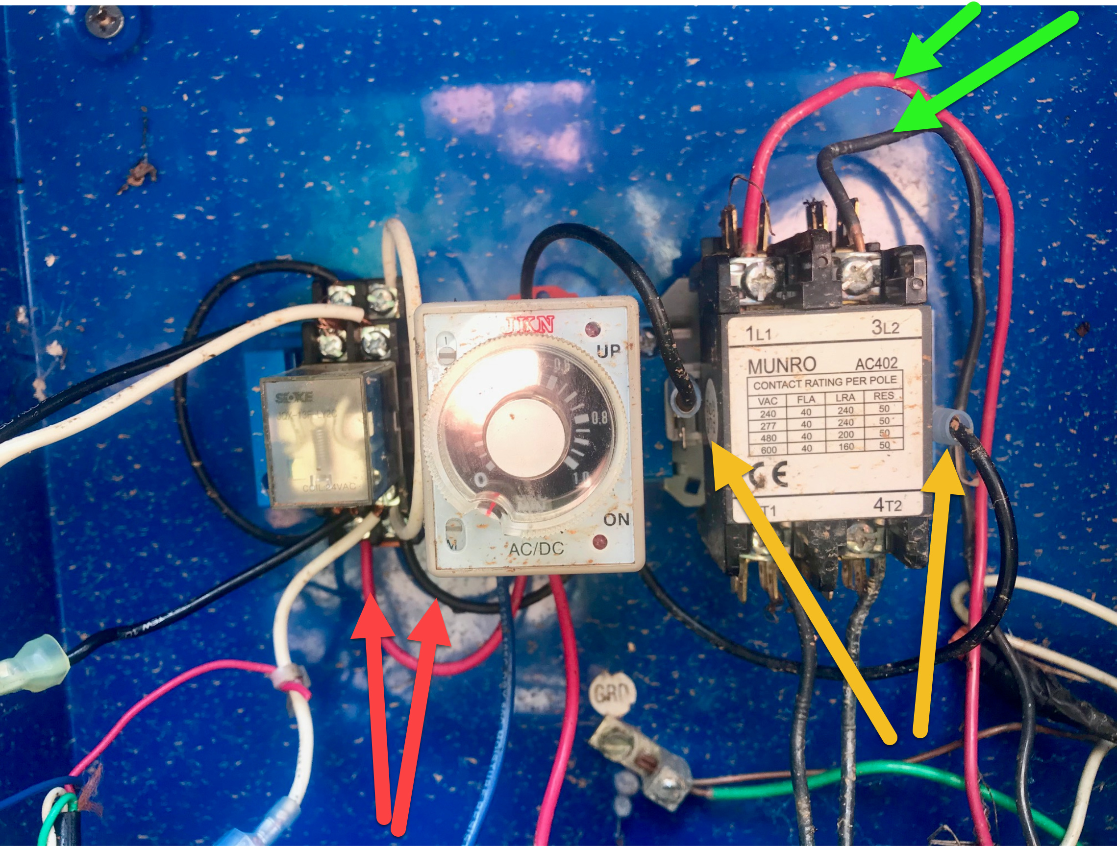
I have been going through this effort for the past 3 years performing a lot of troublshooting:: measing voltage drop, rewiring all wirded connections, running new master value lines, working with Munro support/replacing their relay/testing their circuits, etc – Even thought all this effort - it seems that the Rachio controllers still somehow indicating a ‘Zone fault detected / master value may have wiring issues’. I am 99.99999 % sure at this point all my wiring is top notch / done correctly.

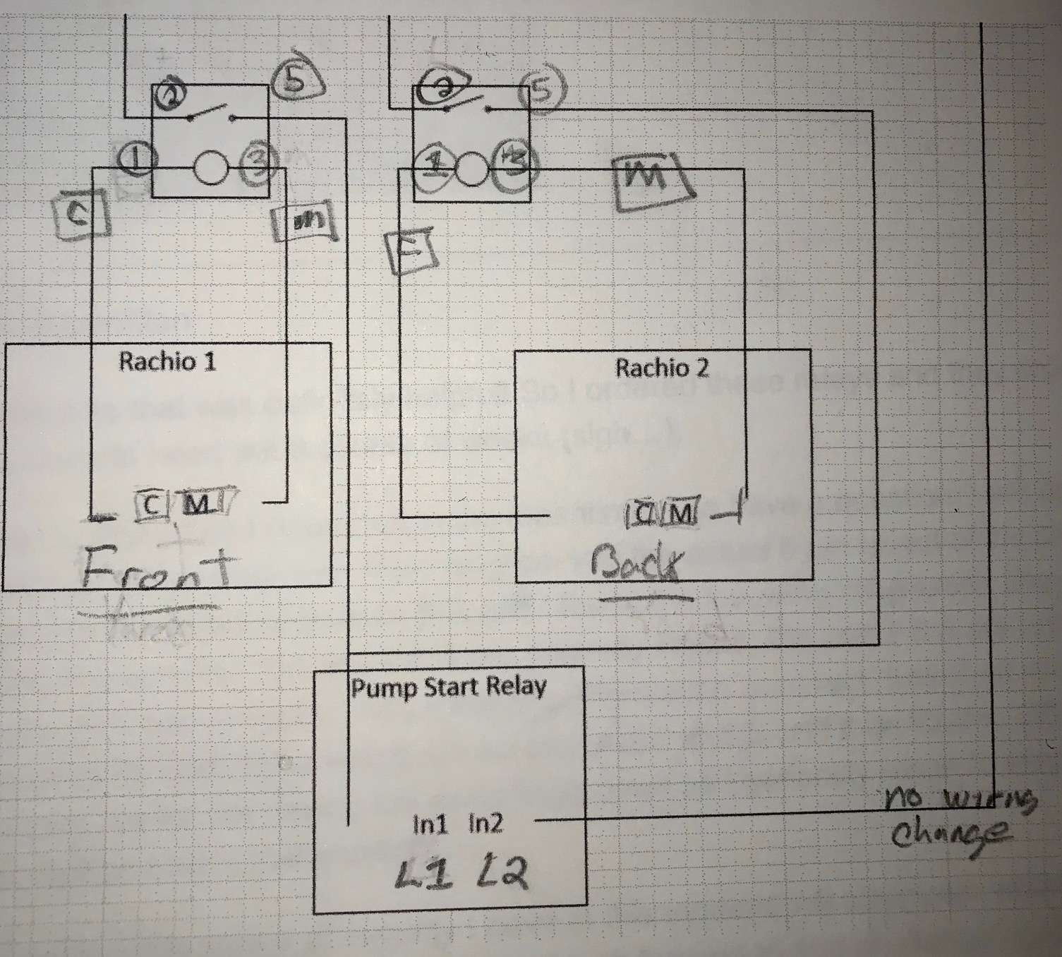
Bottom line: I think the 2 Rachio controllers are getting ‘confused’ by seeing each other being connected to the Munro Smart Relay (controlling the power to the pump, etc) - and causing the fault error. Is that possible?

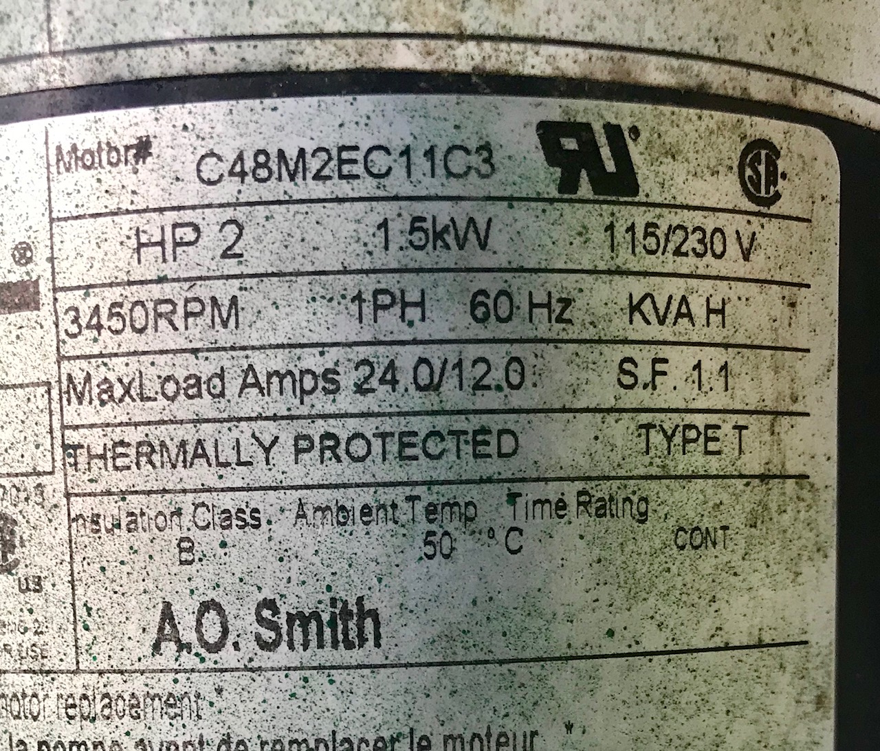
What is happening I have 1 16-zone gen3 controller and 1 8-zone gen 3 controller connected to the Munro Smart Pump relay - with all heavy gauge wire and are all with acceptable voltage drop for the controllers and relay to operate (already been that path with Rachio’s great support teams and Muro’s senior engineer that personally look interested in helping me troubleshoot this). What is happening is that I get RANDOM zone fault messages - stopping the scheduled job or a manual job. It is completely random - as I have tried 1000’s of variations over these 3 years to isolate the problem - rewiring everything, trying different sequences of zone, turning on controllers in different orders, putting time pauses between running zones, making sure jobs are not trying to run at the same time, new replacement solenoids, etc…

I also say that because when this fault occurs – and it’s a lot: once every 3 or 4 cycles at least, if I simply keep restarting the job a couple of times from the app or manually from the controller, it eventually will works – but that usually takes 2 ot 3 faults first – but it will eventually work.

*** My Thoughts about a Solution ***
Through all of this – the error seems to boils down to if when BOTH controllers are connected to the relay, it produces these random fault messages. If only one controller is connected to the smart pump relay - and the other controller is physically disconnected from the Smart Pump Relay, then one connected controller works just fine never generating a fault. In my troublshotting, I have even alternated controllers - same results. I have even the upgraded both controllers from gen 2 to gen 3, tried the combination of these, etc… That was a pricey way to troublshoot - but same results. Bottom line – when both are connected – that’s when the fault errors are triggered.

Additional Considerations: Like I mentioned, I had the issues starting with my Gen 2 controlers - but when I moved to the Gen 3 controllers, I get A LOT more over these fault errors. Leading me to believe it’s something in their SOFTWARE reacting to a voltage/amperage issue triggering this message / shutdown when two controllers are connected to the smart relay. My theory is that controller 1 sees controller 2 over the relay – and that is causing the master fault error condition - and they lowered that threshold for the fault.

My gut is telling me there should be another system flag that Rachio needs to set / trap to deal with two controllers being attached to the Munro Smart Relay. I could be wrong on this – but I am reaching out because there doesn’t seem to be clear answers to questions on using 2 Controllers with the Munro Smart Pump Relay. Perhaps I am missing a setting somewhere (please tell me that is the case!)T

Thus my questions:

Yes or No: Does Gen 2 or Gen 3 work with Munro Smart Pump Relays without showing fault errors?

Yes or No: Has Rachio product / support / dev teams actually tested 2 controllers with the Munro Smart Pump Relays? (again two controllers connected the smart relay)

Yes or No: Has anyone fixed / found a work around for Zone Fault messages when two controllers are connected to the Munro Smart Relay Pump? (are they seeing each other and that could be causing the fault condition to trip)

Thanks for your thoughts and suggestions!

@AngryIrrigationMan - which model of the Munro Smart Pump relay is being used? The reason I ask is in a prior post it was noted there is a lower power drawn Munro model that did work. See →

I’d also consider isolating the controllers from each other using a SPDT relay (approximately $7 on Amazon) as was diagramed/discussed in this post →

If it is truly a current draw issue with the Munro device, then one could use two NO (normally open) SPST (single pole single throw) relays wired in parallel with each relay coil controlled by a different Rachio M terminal. The power from an external power supply (2 Amp +) would go through the Common/pole terminal on the relays with the NO term connected to the Munro pump start signal and the common/return from the Munro back to the external power supply.

So while I don’t work for Rachio, here are the answers to the three questions.

  1. I believe so with a low power draw version as mentioned in earlier in this post.

  2. I doubt it as I would think this would be a rare case for them to spend the time/trouble/effort to test.

  3. See the above solution to isolate the controllers from each other, with or without a beefier external power supply.

1 Like

@DLane A hearty thank you for your detailed reply! Your level of detail was the life-raft and sanity check that I needed - and at the same time made my head hurt! Also thank you for including the other threads as the diagrams were very helpful.

Bottomline: I think you hit the nail on the head - I am using a 220V pump.

With that in mind, I was wonder if you can expand on your reply as you stated the following as a possible way forward:

“If it is truly a current draw issue with the Munro device, then one could use two NO (normally open) SPST (single pole single throw) relays wired in parallel with each relay coil controlled by a different Rachio M terminal. The power from an external power supply (2 Amp +) would go through the Common/pole terminal on the relays with the NO term connected to the Munro pump start signal and the common/return from the Munro back to the external power supply.”

I have two questions:

First - is this the correct NO SPST:
https://www.amazon.com/URBEST-HH52P-Electromagnetic-Power-DYF08A/dp/B00NN5ABG2/ref=pd_cart_vw_crc_1_3/132-3164648-6791922?_encoding=UTF8&pd_rd_i=B00NN5ABG2&pd_rd_r=a6dedbcd-667a-48e5-8257-41a8e73ec429&pd_rd_w=oTDOV&pd_rd_wg=U6iv8&pf_rd_p=7b1a11cb-b9d6-4645-a52e-34c86ca37029&pf_rd_r=N4ZWA8XMJRE28N7WRQPG&psc=1&refRID=N4ZWA8XMJRE28N7WRQPG In case that link doesn’t work, it’s the “URBEST HH52P AC 24V Coil DPDT 8 Pins Electromagnetic Power Relay w DYF08A Base” from Amazon

Second - can you expand more on your quote as I get lost at the second sentence – starting with ‘The power from an external power…’ I think I have it – but I just hate letting the smoke out of these things :blush:

1 Like

@AngryIrrigationMan - you’re welcome! The current draw isn’t related to the current or voltage (a 220v pump will pull about half the amps a 120 volt pump will for the same size) the pump draws, but rather the current the pump start relay needs to close the relay and energize the pump.

Here is a Visio drawing I quickly hacked together.

That relay will work. I prefer a sealed unit like ->

Let me know if you have any other questions.

Again - YMMV.

1 Like

@DLane

1 Like

Many thanks as that was definitely helpful! So I ordered these relays and they arrived - just in time for me to have to head out a couple of weeks (sigh…).

I will work on that when I return but in the meantime, I do have a question: I am not familiar with relays enough to translate your Visio diagram into the actual 6 pin layout of the physical relay. I have been trying to do my homework on this and I found the following information about the relay but I can’t verify it is correct. “Pin pair 2 & 4 are normally closed; Pin pair 2 & 5 are normally open. Pins 1 & 3 are the 24V coil contacts.” Assuming this information is correct, based on your directions, my power source for each relay would run across pins 2 and 5, and then Rachio C/M across the 2 and 4 pins. Forgive me for not having the exact lingo down as I generally resort to simply getting a bigger hammer. But do I have that correct?

I have a feeling this sense of security I have at this moment will disappear when I open the box and start tracing wires in a couple of weeks but I look forward to that challenge! (gulp)

@AngryIrrigationMan - close. Here are the wiring connections:

Rachio C to Relay 1
Rachio M to Relay 3
Power supply lead to Relay 2
Lead from relay to pump start relay to Relay 5

and then the other side of the pump start relay trigger line back to the other line on the power supply.

There should be numbers by the pins on the relay (I think). If not number then NC - normally closed (pin 4), C - common (pin 2), NO - normally open (pin 5) and the other two would be for the coil. Also a ohm meter can be used to identify pins if necessary.

You’ve got this. Safe travels and have fun. We’ll be here if there are any questions when you get back.

Please post the results (success!) when it is installed and working.

1 Like

Ok - after some delays, I am finally back in action and about ready to tackle this. Two things - here is the schematic for the Munro system: Is there anything on this that would indicate a different wiring setup?

I have started to pre-wire and label as much as I can. Here is the basic rig setup (just relays on a board):

Last but not least, here is the actual current setup - where the rubber meets the road:

My question is - how do I weave in the pressure and tempature switch here? My gut is telling me I have to do something with the wires with the RED arrows here:

@AngryIrrigationMan - sorry for the delay in responding, been traveling and busy.

I believe the correct connections are on the relay to the left of the JKN time delay device. The connections are listed as 1, 4, 13 and 14 on the wiring diagram. Check to see where the wires for the top two terminals on each side go. I’m guessing they go back to the current controllers.

It looks like one can wire the Front relay to 1 and the back relay to 14 with the common return to the separate power supply to 4 and 13 and not have to join the output from the relays together. Or one can join the wires together and just use terminals 1 and 4.

@Gene, did I Bozo anything here?

Thanks for the initial insights on that on the pressure/temp switches - and while that is brewing, let me give you a status update: So I wired everything in but I couldn’t get the pump to turn on. I could hear the relays activate when I turned on each controller but the pump wouldn’t turn on. I didn’t have time to see if I had any voltage out of Relay pin 5 - as I was running out of daylight and I realized they just seeded/couldn’t miss a cycle tonight. So I disconnected my rig and reconnected the old setup to get through the night (worked just fine then). I’ll try again tomorrow as I’ll have more time to troubleshoot (make sure I double check all my connections correct, etc…).

By the way, I marked up your Visio driagram with the following to make sure I have things correct:

@AngryIrrigationMan your drawing looks good, but you should be using terminal 4 instead of 5 on the Supco relays. Terminal 4 is your “input”, 2 is Normally Open (NO) “output”, 5 is Normally Closed (NC) “output”. You are driving them correctly with terminals 1 and 3, thus you can hear the relay click.

@DLane Got lost in the wiring diagram, would have to investigate what every relay actually is on the old timer/temperature board in order to provide any feedback. What you’ve wrote seems good, lets try it and see :wink:

1 Like

Update: I switched to terminal 4 from terminal 5 - no luck as the pump will not turn on. With my volt meter, I do have voltage going to the Pump Start Relay from terminal 4 when a controller is turned on - but the pump doesn’t turn on. Does this mean I have the wrong relays that may not be passing enough amps/volts through them?

Here are the specs of the pump:

FYSA: I need to retest everying in the morning. When I was testing the new relay rig today, I disconnected the YELLOW arrows above (the connections from the Pump Relay to the JKN timer) to make sure that wasn’t causing any issues with the new relays. BUT what I just discovered was that old setup also does NOT work with those disconnected. So I will reconnect those with the new relay rig setup tomorrow - and I’ll keep eveyone posted.

@AngryIrrigationMan - I’m betting that when the wires are connected back form the JKN timer to the pump relay it will work. If there is current (24 VAC???) on those wires I think that is what causes the relay to close. If the wires are still disconnected and the Rachio is run is there a voltage potential between those two wires?

I believe the JKN device keeps the pump from rapidly restarting (i.e power outage, multiple units, etc.) and integrates the pressure and temperature switches. If everything is ok, then it provides power to the relay unit.

Thanks for the update. I think you’re very, very close.

@Gene - lost?? Tell me it isn’t so. Also, great catch on the relay terminals!

@DLane, lets just say that schematic shown on the cover of the Munro box has raised more questions than it has answered :slight_smile: I’m actually away in Europe as well, didn’t want to go down that rabbit hole just yet :wink:

Update: I tried the relay rig with the wires to the timer connected - no luck. Same results as before: hearing the relays turn on/off - and voltage out of terminal 4: but the pump doesn’t turn on. I’ll try to shoot a video of my wiring to see if something catches your eye.

FYI - I shot a movie but it’s too large for me to post but I don’t think it shows anything noteworthy.

OK, after another look at the smart box that you have, I see that the relay on the left has the same pinout as those I usually recommend, that makes understanding everything easier.

The problem is that your old setup already has provision for a 24V input to drive internal output and run the pump. Currently that input is left unused, thus the Munro smart box does not let your pump to turn on.

Solution is to try hooking everything up through the original instructions on the cover. You would not need to use the two new relays and instead drive the on-board inputs that come with your smart box.

Hello @Gene! When I do that (use the old setup - I am very familar with that), I get the same errors from Rachio as in my original post: To summarize that: 8 out of 10 times when I turn a controller on or it runs on a schedule - it fails as I get the Rachio error messages that ‘Zone fault detected on controller X’. I have changed/checked all solioids, I ran thicker guage wire to ensure sufficient voltage from the controllers to the Munro box, etc… Also if I disconnect either controller, it works just fine with no wiring fault errors, etc… At first I thought it was a software item - but you can see that all above.